LDP-IGP Synchronization
This chapter provides information about LDP-IGP synchronization
Topics in this chapter include:
Applicability
This chapter was initially written for SR OS Release 14.0.R6, but the CLI in the current edition is based on SR OS Release 21.2.R1.
Label Distribution Protocol - Interior Gateway Protocol (LDP-IGP) synchronization based on RFC 5443 is supported in SR OS Release 6.0, and later. LDP end-of-Label Information Base (LIB), as described in RFC 5919, is supported in SR OS Release 14.0.R1, and later.
Overview
Within an MPLS network using LDP, it is common practice to enable a synchronization timer between LDP and the IGP to give both the IGP and LDP time to converge after a link is restored. Without LDP-IGP synchronization, the IGP and LDP converge independently. Because the IGP converges before LDP, traffic can be black-holed until LDP has converged. When the IGP converges after link restoration and a new next hop is available, this change in next hop causes LDP to stop using the LDP labels for the alternate path. After the adjacency with the new next hop is established, labels are allocated for the new shortest (primary) path. These new labels are not yet signaled by LDP, causing the traffic to be black-holed for all or part of the FECs until LDP converges.
LDP-IGP synchronization based on RFC 5443 consists of temporarily setting the run-time IGP cost of a restored link to infinity to give time for both IGP and LDP to converge. When the LDP synchronization timer expires, the runtime IGP cost is restored to the configured IGP cost and IGP will re-advertise it and use this for the next shortest path first (SPF) computation. The value for infinity of the IGP cost for a router interface depends on the IGP: 0xFFFF (65535) for OSPF, 0x3F (63) for IS-IS regular metric, and 0xFFFFFE (16777214) for IS-IS wide metric. LDP-IGP synchronization is not supported on RIP interfaces.
When the system converges, the IGP starts the LDP synchronization timer when the LDP session to the neighbor is established over the interface. The LDP synchronization timer is running during the exchange of label FEC bindings over the interface. When the LDP synchronization timer expires, the IGP announces the new best next hop and LDP uses this next hop if the label bindings for the neighbor's FEC are available. However, the LDP synchronization timer does not guarantee that all FEC bindings will be exchanged when the timer expires. Operators do not want to configure very large timers on every node, which may result in long synchronization times. The end-of-lib option (RFC 5919) reduces the synchronization time; therefore, operators can configure large synchronization timers that will be aborted when the end-of-lib notification has been received from a downstream node.
By default, LDP-IGP synchronization is enabled for OSPF and for IS-IS, as follows:
*A:PE-1>configure
    router
        ospf
            info detail | match ldp-sync

shows:                no disable-ldp-sync
*A:PE-1>configure
    router
        isis
            info detail | match ldp-sync

shows:                no disable-ldp-sync
By default, LDP synchronization is disabled (out-of-service) on each interface, as follows:
A:PE-1# show router ospf interface "int-PE-1-P-2" detail | match Ldp
Ldp Sync         : outOfService         Ldp Sync Wait    : Disabled
Ldp Timer State  : Disabled             Ldp Tm Left      : 0
A:PE-1# show router isis interface "int-PE-1-P-2" detail | match Ldp
Ldp Sync        : outOfService                    Ldp Sync Wait   : Disabled
Ldp Timer State : Disabled                        Ldp Tm Left     : 0
LDP end-of-lib, as defined in RFC 5919, allows a downstream node to notify its upstream peer that the node has advertised its entire LIB to its upstream peer, which can terminate the LDP synchronization timer. LDP end-of-lib notifications use a FEC TLV with the type wildcard FEC element for all negotiated FEC types. LDP end-of-lib is sent even if the system has no label bindings to advertise. Each node notifies its peer nodes that it is safe to send LDP end-of-lib notifications even if the node is not configured to process them. The node sends an unrecognized notification capability TLV (RFC 5919) in the initialization message, indicating that it will ignore notification messages that carry status TLV with a non-fatal status code unknown to it.
The LDP synchronization timer is configured in seconds with a maximum of 1800 seconds on a per interface basis, as follows:
*A:PE-1>configure
    router
        interface "int-PE-1-P-2"
            ldp-sync-timer ?
  - ldp-sync-timer <seconds> [end-of-lib]
  - no ldp-sync-timer

 <seconds>            : [1..1800]
 <end-of-lib>         : keyword
As an example, an LDP synchronization timer of 300 seconds can be configured on interface "int-PE-1-P-2", with or without the LDP end-of-lib option, as follows:
# on PE-1:
configure
    router
        interface "int-PE-1-P-2"
            ldp-sync-timer 300
            exit all
# on PE-1:
configure
    router
        interface "int-PE-1-P-2"
            ldp-sync-timer 300 end-of-lib
            exit all
When the end-of-lib option is not configured, the LDP synchronization timer is started when the LDP hello adjacency comes up over the interface. Any received LDP end-of-lib message is ignored.
When the end-of-lib option is configured, the receiving node behaves as follows:
The LDP synchronization timer is started when the LDP hello adjacency comes up over the interface.
When LDP end-of-lib type wildcard FEC messages have been received for all negotiated FEC types for a certain session to an LDP peer for the IGP interface, the LDP synchronization timer is terminated and the system restores the IGP link cost.
If the LDP synchronization timer expires before the LDP end-of-lib messages are received for all negotiated FEC types, the system restores the IGP link cost.
All unexpected LDP end-of-lib messages are dropped.
When the end-of-lib option is configured, the sending node will advertise an LDP end-of-lib message for all FECs (prefix and P2MP FECs) after all FECs are sent for all peers that have advertised the unrecognized notification capability TLV.
When a user changes the IGP cost of an interface, the new value is advertised at the next flooding of link attributes by the IGP. If the LDP synchronization timer is running, the new cost value will only be advertised after the timer expires. However, the following tools or configure commands can be used to terminate the LDP-IGP synchronization, causing the new IGP cost value to be advertised instantly.
The following two tools commands do not modify the configuration; they terminate the LDP synchronization timer and restore the actual cost of the IGP interface:
tools perform router ospf ldp-sync-exit
tools perform router isis ldp-sync-exit
The following three commands disable the LDP-IGP synchronization entirely, either from the interface or globally for the IGP (OSPF or IS-IS):
# on PE-1:
configure
    router
        interface "int-PE-1-P-2"
            no ldp-sync-timer
configure
    router
        ospf
            disable-ldp-sync
configure
    router
        isis
            disable-ldp-sync
If the user changes the value of the LDP synchronization timer parameter, the new value will take effect at the next synchronization event. If the timer is still running, it will continue to use the previous value.
Configuration
Example topology shows the example topology.
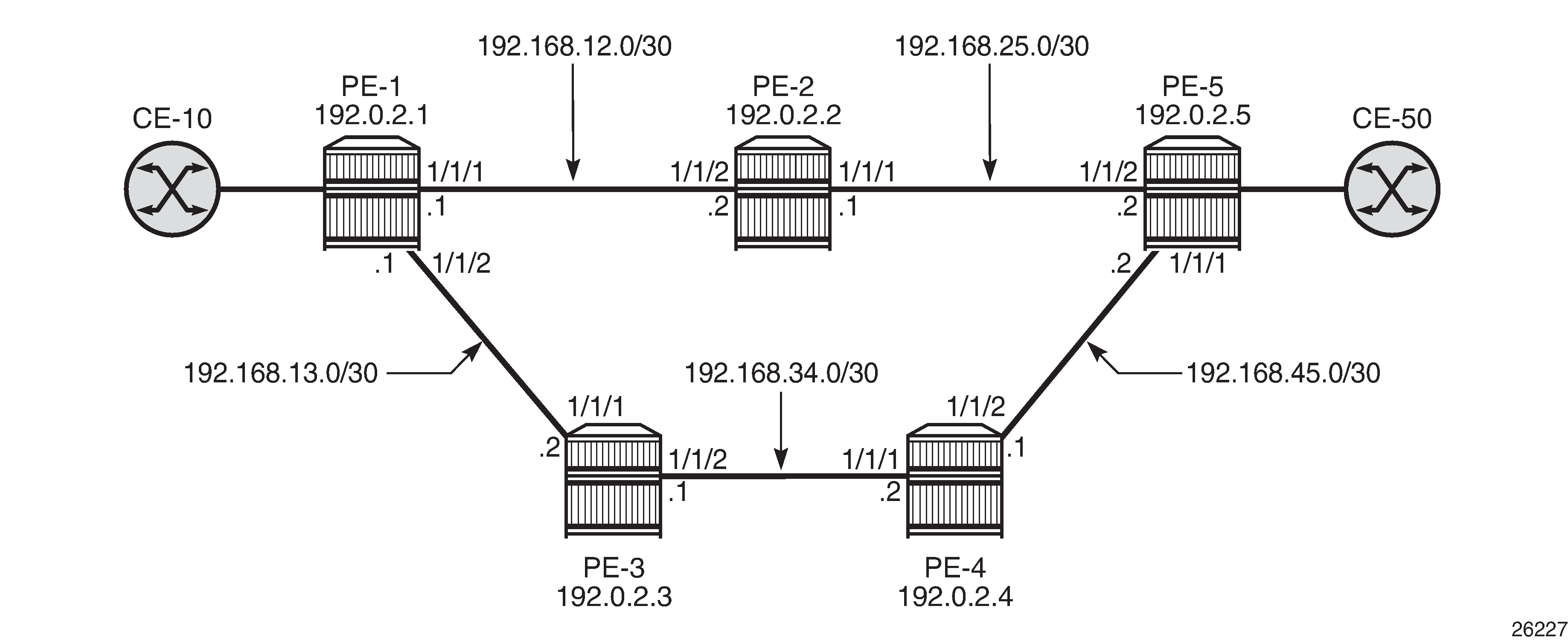
The initial configuration on these nodes includes the following:
Cards, MDAs, ports
Router interfaces
IGP: OSPF on all interfaces between the five P/PE routers (alternatively, IS-IS can be configured)
LDP on all interfaces (LDP link adjacencies)
Services on the PEs; for example, an Epipe between PE-1 and PE-5 (LDP targeted adjacencies)
In this example topology, CE-10 and CE-50 correspond to VPRN_10_name on PE-1 and PE-5 using a hairpin to loop the traffic back to the node.
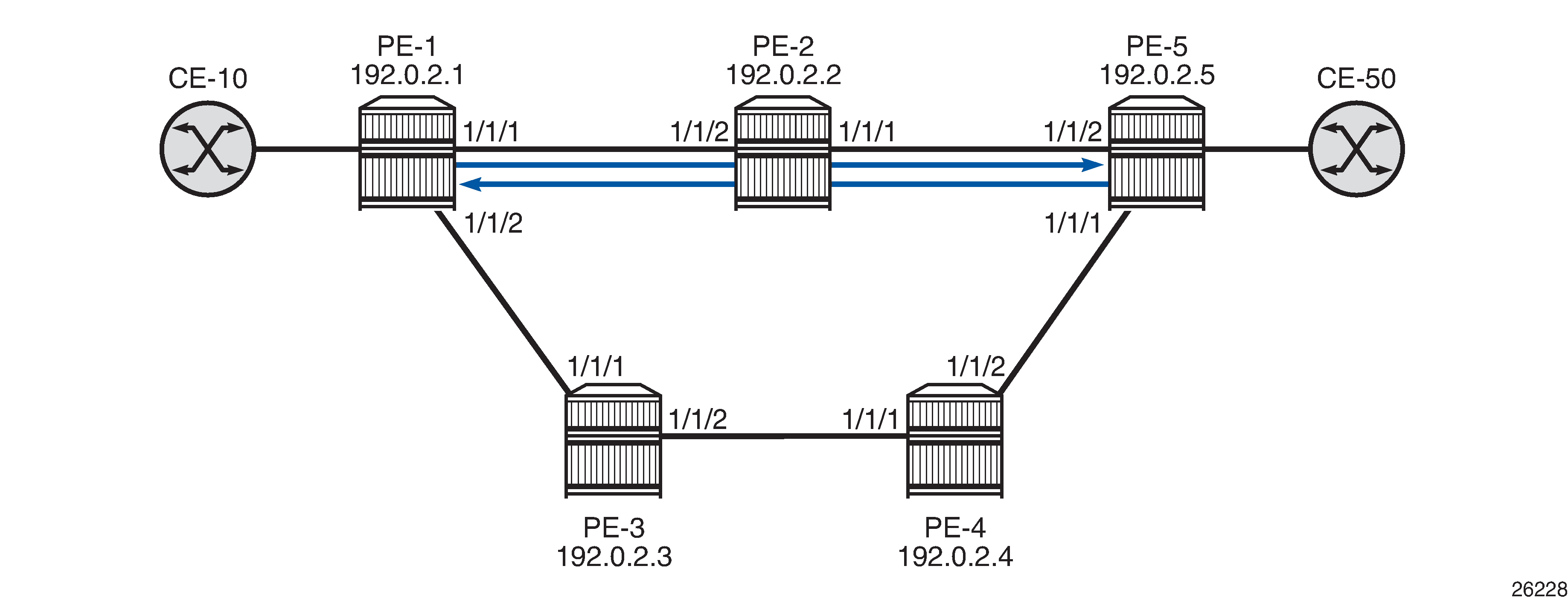
Default IGP metrics are used on the interfaces and, under normal conditions, traffic between CE-10 and CE-50 is sent over the shortest path via P-2, as shown in Shortest path between PE-1 and PE-5.
LDP-IGP synchronization without LDP end-of-lib
LDP-IGP synchronization is, by default, globally enabled for OSPF and IS-IS, but disabled on every interface. In this example, LDP-IGP synchronization will be configured with an LDP synchronization timer of 300 seconds on all the interfaces in all the nodes, as follows:
# on PE-1:
configure
    router
        interface "int-PE-1-P-2"
            ldp-sync-timer 300
        exit
        interface "int-PE-1-P-3"
            ldp-sync-timer 300
        exit
        exit all
# on P-2:
configure
    router
        interface "int-P-2-PE-1"
            ldp-sync-timer 300
        exit
        interface "int-P-2-PE-5"
            ldp-sync-timer 300
        exit
        exit all
The configuration is similar on the other nodes. With this configuration, a restored interface will temporarily get an IGP cost of infinity; therefore, the link will not be used for data traffic until the LDP synchronization timer terminates (when it expires after 300 seconds or when it is terminated manually). To simulate a link failure, port 1/1/1 is disabled (shutdown) and re-enabled (no shutdown) on PE-1, as follows:
# on PE-1:
configure
    port 1/1/1
        shutdown
    exit
    exit all

configure
    port 1/1/1
        no shutdown
    exit
    exit all
The LDP synchronization timer is not started before the LDP hello adjacency is established. The following output shows the port re-enabled, but before the LDP adjacency is established (Ldp Timer State = Wait for Ldp Adj.):
*A:PE-1# show router ospf interface "int-PE-1-P-2" detail | match Ldp
Ldp Sync         : inService            Ldp Sync Wait    : Disabled
Ldp Timer State  : Wait for Ldp Adj.    Ldp Tm Left      : 0
The following debug messages for OSPF show that the OSPF interface state is up (point-to-point), the LDP Sync Timer state is updated to ‟WAIT_FOR_ADJ”, and afterward the LDP state is updated to ‟LDP_INTF_HAS_ADJ”, as follows:
21 2021/07/30 08:46:42.594 UTC MINOR: DEBUG #2001 Base OSPFv2
"OSPFv2: INTF
IF 192.168.12.1 Idx 2 Event: IF_UP state: from DOWN to PTP"

25 2021/07/30 08:46:42.594 UTC MINOR: DEBUG #2001 Base OSPFv2
"OSPFv2: INTF
Updated the LDP Sync Timer state for I/F 2 to WAIT_FOR_ADJ"

26 2021/07/30 08:46:46.235 UTC MINOR: DEBUG #2001 Base OSPFv2
"OSPFv2: INTF
OSPF I/F 2 LDP state: new LDP_INTF_HAS_ADJ old LDP_INTF_DOWN"
When the LDP hello adjacency is established, the interface between PE-1 and P-2 gets an IGP cost of infinity and the LDP synchronization timer is started, as follows:
27 2021/07/30 08:46:46.235 UTC MINOR: DEBUG #2001 Base OSPFv2
"OSPFv2: INTF
Updated the LDP Sync Timer state for I/F 2 to TMR_ACTIVE"
LDP bindings are exchanged as follows, but no message indicates the end-of-lib (and if it were sent by P-2, it would be ignored by PE-1). The LDP synchronization timer is not automatically terminated when the LDP bindings are received, because the configuration does not include the end-of-lib option.
28 2021/07/30 08:46:46.418 UTC MINOR: DEBUG #2001 Base LDP
"LDP: Binding
Sending Label mapping label 524287 for Prefix Address Family = 1 Prefix = 192.0.2.1/32 to peer 192.0.2.2:0. "

30 2021/07/30 08:46:46.418 UTC MINOR: DEBUG #2001 Base LDP
"LDP: Binding
Sending Label mapping label 524284 for Prefix Address Family = 1 Prefix = 192.0.2.3/32 to peer 192.0.2.2:0. "

32 2021/07/30 08:46:46.418 UTC MINOR: DEBUG #2001 Base LDP
"LDP: Binding
Sending Label mapping label 524283 for Prefix Address Family = 1 Prefix = 192.0.2.4/32 to peer 192.0.2.2:0. "

34 2021/07/30 08:46:46.418 UTC MINOR: DEBUG #2001 Base LDP
"LDP: Binding
Sending Label mapping label 524282 for Prefix Address Family = 1 Prefix = 192.0.2.5/32 to peer 192.0.2.2:0. "
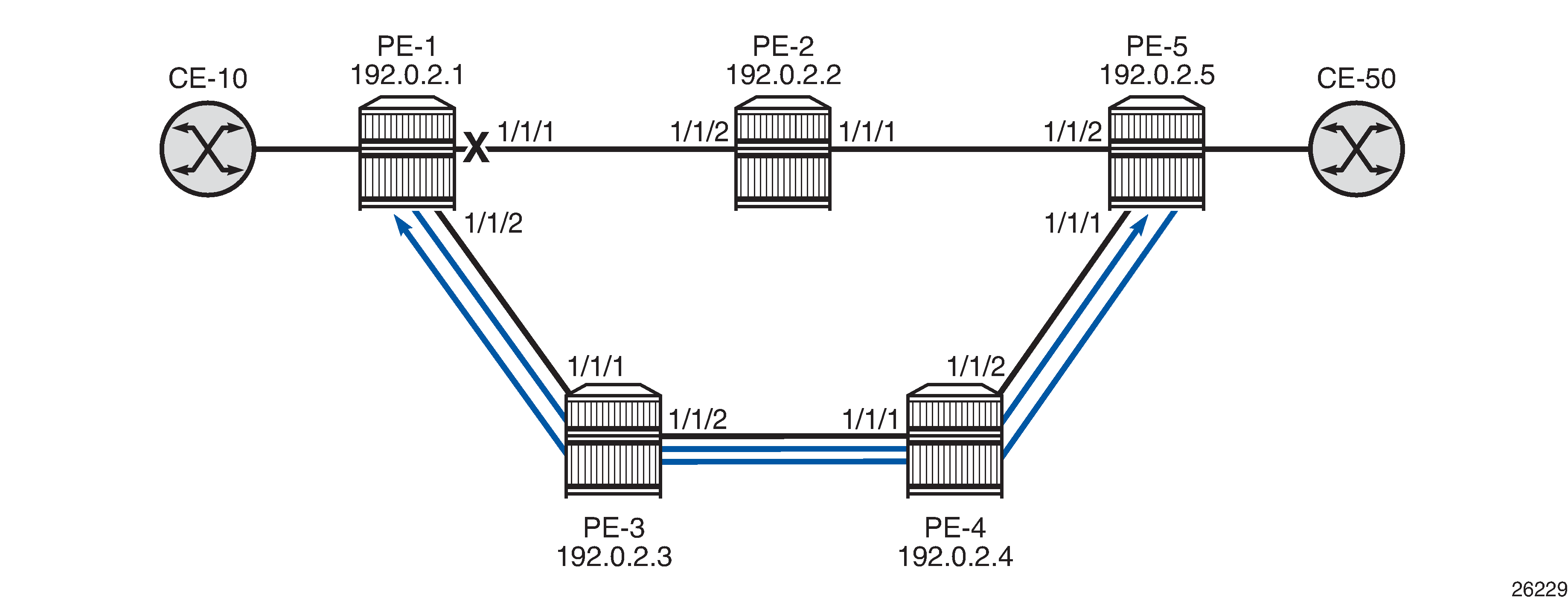
As long as the LDP synchronization timer is not terminated, traffic between CE-10 and CE-50 is redirected to the path via P-3 and P-4, as shown in Rerouting via P-3 and P-4 until LDP synchronization timer terminates.
The following commands for the OSPF interfaces between PE-1 and P-2 show the Ldp Timer State = Timer Active, Ldp Sync Wait = Enabled; therefore, traffic is rerouted and the remaining time (Ldp Tm Left):
*A:PE-1# show router ospf interface "int-PE-1-P-2" detail | match Ldp
Ldp Sync         : inService            Ldp Sync Wait    : Enabled
Ldp Timer State  : Timer Active         Ldp Tm Left      : 298
*A:P-2# show router ospf interface "int-P-2-PE-1" detail | match Ldp
Ldp Sync         : inService            Ldp Sync Wait    : Enabled
Ldp Timer State  : Timer Active         Ldp Tm Left      : 271
The restored interface between PE-1 and P-2 will have an infinite IGP cost, so will not be used for data traffic as long as the LDP synchronization timer is active. All traffic between the CEs takes the path via P-3 and P-4, which can be verified as follows. The port statistics are cleared and 1000 ICMP echo requests are sent by CE-10 to CE-50. On PE-1, port 1/1/1 is used toward P-2 and port 1/1/2 is used toward P-3. All traffic is expected to take the path toward P-3. However, there will be some IGP and LDP signaling on all interfaces, so the packet count will be slightly greater than 1000, as follows:
*A:PE-1# clear port 1/1/[1..2] statistics
*A:PE-1# ping router 10 172.16.10.2 rapid count 1000
PING 172.16.10.2 56 data bytes
---snip---
---- 172.16.10.2 PING Statistics ----
1000 packets transmitted, 1000 packets received, 0.00% packet loss
round-trip min = 1.61ms, avg = 1.80ms, max = 3.59ms, stddev = 0.213ms
*A:PE-1# show port 1/1/1 statistics

===============================================================================
Port Statistics on Slot 1
===============================================================================
Port                        Ingress Packets                  Ingress Octets
Id                           Egress Packets                   Egress Octets
-------------------------------------------------------------------------------
1/1/1                                    20                            2219
                                         21                            2305
===============================================================================

*A:PE-1# show port 1/1/2 statistics

===============================================================================
Port Statistics on Slot 1
===============================================================================
Port                        Ingress Packets                  Ingress Octets
Id                           Egress Packets                   Egress Octets
-------------------------------------------------------------------------------
1/1/2                                  1046                          128326
                                       1047                          128421
===============================================================================
The port statistics on the other nodes will also show that these packets are sent via P-3 and P-4 instead of via P-2.
Even though the LIB was exchanged within seconds, the restored link only gets its normal IGP cost after the LDP synchronization timer has terminated. This can be done manually for a specific IGP (in this example, for OSPF on interface "int-PE-1-P-2" on PE-1) as follows:
*A:PE-1# tools perform router ospf ldp-sync-exit
Done.
*A:PE-1# show router ospf interface "int-PE-1-P-2" detail | match Ldp
Ldp Sync         : inService            Ldp Sync Wait    : Disabled
Ldp Timer State  : Manual Exit          Ldp Tm Left      : 0
The LDP synchronization timer can be configured independently for each IGP on each interface. The LDP synchronization timer for OSPF on interface "int-PE-1-P-2" is terminated manually (Ldp Timer State = Manual Exit; Ldp Sync Wait = Disabled; Ldp Tm Left = 0). Traffic from CE-10 to CE-50 can use interface "int-PE-1-P-2" because that interface has its configured (default) IGP cost. However, traffic from CE-50 to CE-10 will not use interface "int-P-2-PE-1" because that interface still has an infinite IGP cost as long as the LDP synchronization timer is not terminated; therefore, traffic toward CE-10 will pass via P-3 instead. This leads to an asymmetric traffic flow: the shortest path from CE-10 to CE-50 is via P-2, while the shortest path from CE-50 to CE-10 is via P-4 and P-3, as shown in Restored link with one LDP synchronization timer terminated.
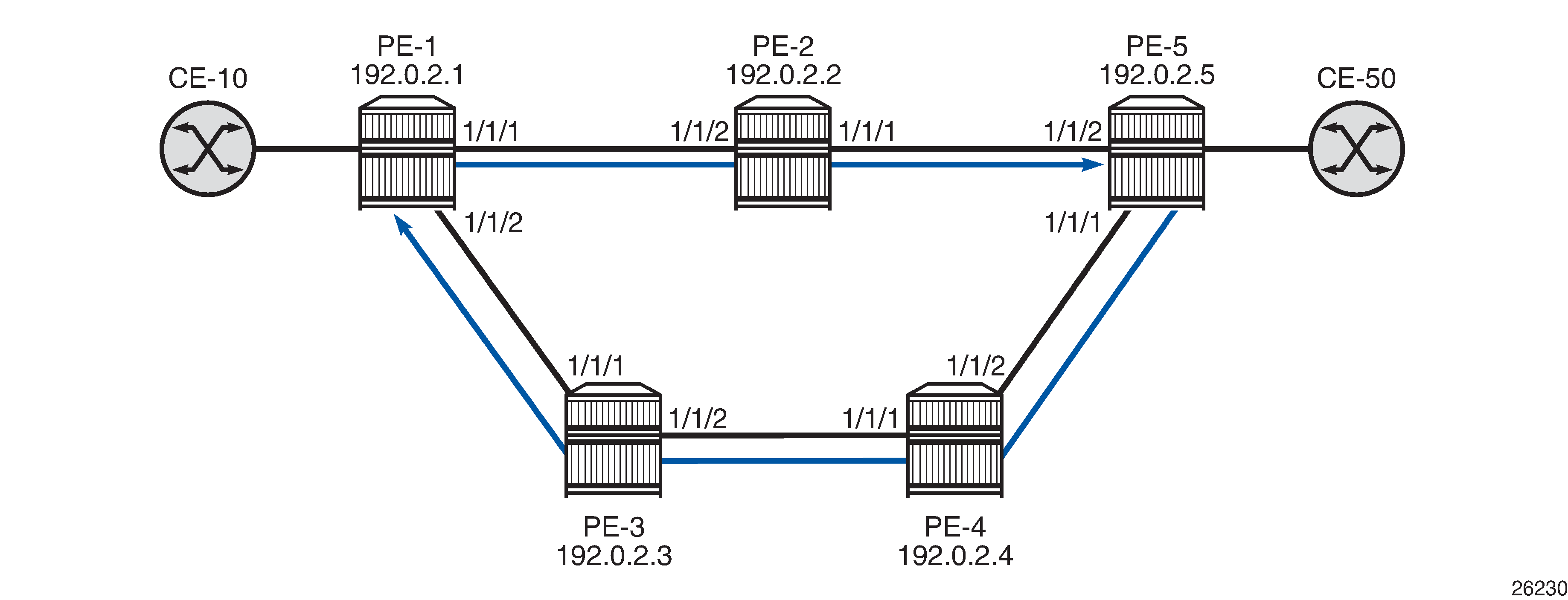
When the second LDP synchronization timer is also terminated, the shortest path is via P-2 for all traffic between CE-10 and CE-50.
The LDP synchronization timer needs to be configured to a value that is long enough to prevent traffic being black-holed, but not too long to cause unnecessary suboptimal routing after the LIB has been exchanged and before the termination of the LDP synchronization timer. The end-of-lib option reduces the LDP synchronization time when the configured LDP synchronization timer is longer than required for the exchange of the LIB, as described in the next section.
LDP synchronization is disabled on the interfaces of PE-1, as follows:
# on PE-1:
configure
    router
        interface "int-PE-1-P-2"
            no ldp-sync-timer
        exit
        interface "int-PE-1-P-3"
            no ldp-sync-timer
        exit
        exit all
Similar commands to disable LDP synchronization on an interface can be configured on the other nodes.
LDP-IGP synchronization with LDP end-of-lib
The LDP synchronization is configured with the end-of-lib option on all interfaces on all nodes; for example, for PE-1, as follows:
# on PE-1:
configure
    router
        interface "int-PE-1-P-2"
            ldp-sync-timer 300 end-of-lib
        exit
        interface "int-PE-1-P-3"
            ldp-sync-timer 300 end-of-lib
        exit
        exit all
The configuration on the other nodes is similar.
A link failure is simulated by disabling and re-enabling port 1/1/1 on PE-1. Initially, the Ldp Timer State is ‟Wait for Ldp Adj.”, as follows:
# on PE-1:
configure
    port 1/1/1
        no shutdown
    exit
    exit all
*A:PE-1# show router ospf interface "int-PE-1-P-2" detail | match Ldp
Ldp Sync         : inService            Ldp Sync Wait    : Disabled
Ldp Timer State  : Wait for Ldp Adj.    Ldp Tm Left      : 0
After the LDP hello adjacency is established on the restored link, the LDP synchronization timer is started and PE-1 sends all LDP bindings to its peer P-2, as follows:
26 2021/07/30 09:02:53.635 UTC MINOR: DEBUG #2001 Base OSPFv2
"OSPFv2: INTF
OSPF I/F 2 LDP state: new LDP_INTF_HAS_ADJ old LDP_INTF_DOWN"

27 2021/07/30 09:02:53.635 UTC MINOR: DEBUG #2001 Base OSPFv2
"OSPFv2: INTF
Updated the LDP Sync Timer state for I/F 2 to TMR_ACTIVE"

32 2021/07/30 09:02:53.898 UTC MINOR: DEBUG #2001 Base LDP
"LDP: Binding
Sending Label mapping label 524284 for Prefix Address Family = 1 Prefix = 192.0.2.3/32
 to peer 192.0.2.2:0."

34 2021/07/30 09:02:53.898 UTC MINOR: DEBUG #2001 Base LDP
"LDP: Binding
Sending Label mapping label 524283 for Prefix Address Family = 1 Prefix = 192.0.2.4/32
 to peer 192.0.2.2:0."

36 2021/07/30 09:02:53.898 UTC MINOR: DEBUG #2001 Base LDP
"LDP: Binding
Sending Label mapping label 524282 for Prefix Address Family = 1 Prefix = 192.0.2.5/32
 to peer 192.0.2.2:0."

38 2021/07/30 09:02:53.922 UTC MINOR: DEBUG #2001 Base OSPFv2
"OSPFv2: INTF
OSPF I/F 2 LDP state: new LDP_LBL_EXCH_DONE old LDP_INTF_HAS_ADJ"

39 2021/07/30 09:02:53.922 UTC MINOR: DEBUG #2001 Base OSPFv2
"OSPFv2: INTF
Updated the LDP Sync Timer state for I/F 2 to EXCH_DONE"

40 2021/07/30 09:02:54.073 UTC MINOR: DEBUG #2001 Base LDP
"LDP: Binding
Sending Label mapping label 524287 for Prefix Address Family = 1 Prefix = 192.0.2.1/32
 to peer 192.0.2.2:0."
When a downstream node has sent its entire LIB to its upstream peer, the node sends an end-of-lib (RFC 5919) notification. When the upstream peer receives an end-of-lib notification from its downstream peer, LDP is considered to be fully operational for the link. LDP triggers the IGP to advertise the link with normal cost instead of infinity and transit traffic can be sent on the restored link. In the preceding debug messages, the LDP Sync Timer state changes to ‟EXCH_DONE”; in the following show command output, the LDP Timer State changes to ‟Label Exchg. Done”:
*A:PE-1# show router ospf interface "int-PE-1-P-2" detail | match Ldp
Ldp Sync         : inService            Ldp Sync Wait    : Disabled
Ldp Timer State  : Label Exchg. Done    Ldp Tm Left      : 0
The LDP synchronization timer is terminated when the entire LIB is exchanged. In this example setup, the LDP synchronization time is reduced from 300 seconds to less than 10 seconds after enabling LDP end-of-lib.
Conclusion
LDP-IGP synchronization (RFC 5443) allows directly connected nodes to delay the use of a restored link for transit IP packets until the LDP labels have been exchanged. RFC 5919 adds the end-of-lib option that reduces the LDP synchronization time to the minimum, so operators can configure large values for the LDP synchronization timer.