Tunneling of ICMP Reply Packets over MPLS LSPs
This chapter provides information about tunneling of ICMP reply packets over MPLS LSPs.
Topics in this chapter include:
Applicability
This chapter is applicable to SR OS routers and was initially written for SR OS Release 13.0.R7. The CLI in the current edition corresponds to SR OS Release 23.3.R1. Internet Control Message Protocol (ICMP) tunneling over Multi-Protocol Label Switching (MPLS) Label Switched Paths (LSPs) is supported in SR OS Release 12.0.R4 or later.
Overview
In IP forwarding, Time-To-Live (TTL) is a well-known mechanism to mitigate the damage in case of a loop. The TTL value in the IP header is decremented by one at each hop and the packet is discarded when the TTL equals 0. TTL is also used in traceroute, where the first batch of echo requests are sent with TTL equal to 1, the second batch of echo requests is sent with TTL equal to 2, and so on. Any intermediate node where the TTL expires (is decremented to 0) sends an ICMP reply of type "Time exceeded" (type 11) to the sender. From the replies, the sequence of hops can be determined.
If ICMP messages are sent in an MPLS tunnel, in pipe mode, the hops in the tunnels are invisible and the TTL is only decremented by the Label Edge Routers (LERs), not by the intermediate Label Switching Routers (LSRs). However, there are two modes for TTL handling, according to RFC 3443, Time To Live Processing in MPLS Networks:
Uniform mode: the MPLS network is visible from the outside. MPLS nodes use the TTL in the same way as any other IP node.
Pipe mode: the MPLS network is invisible from the outside. MPLS use of TTL is independent from IP TTL use. The network appears like a pipe between ingress Label Edge Router (iLER) and egress Label Edge Router (eLER).
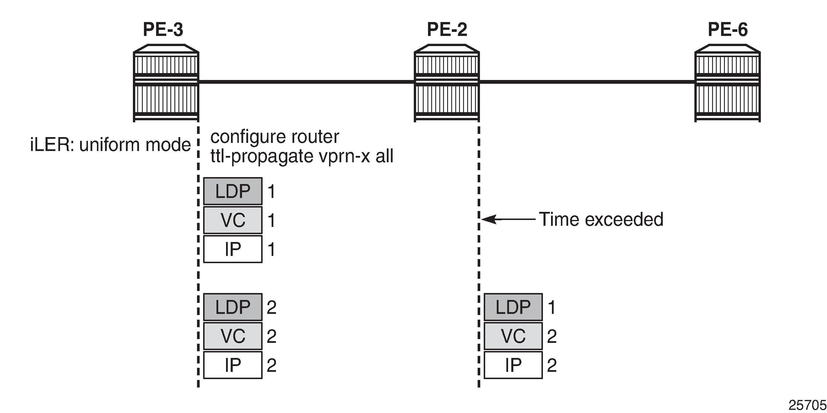
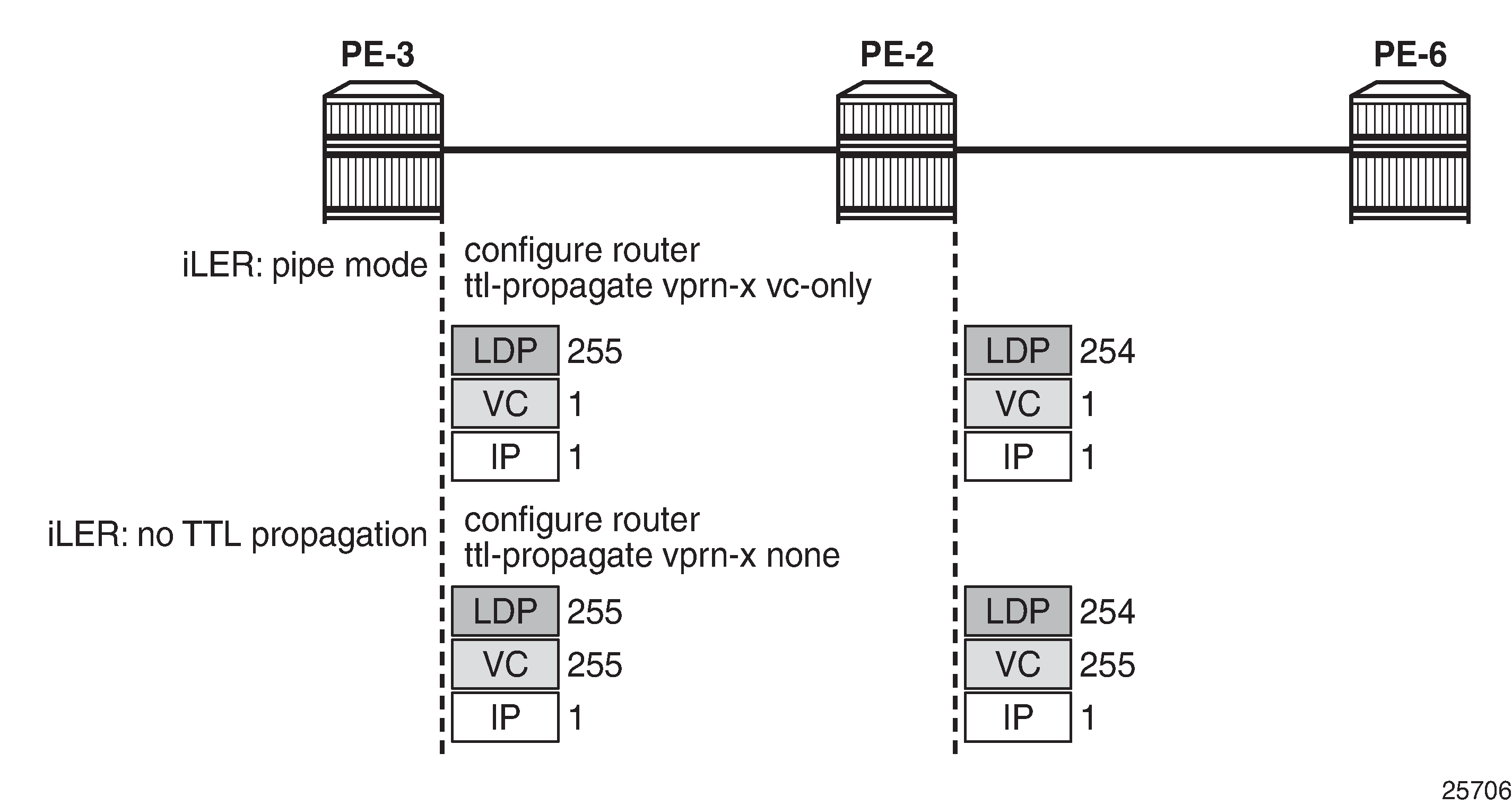
Both TTL uses are shown in Use of TTL: uniform versus pipe:
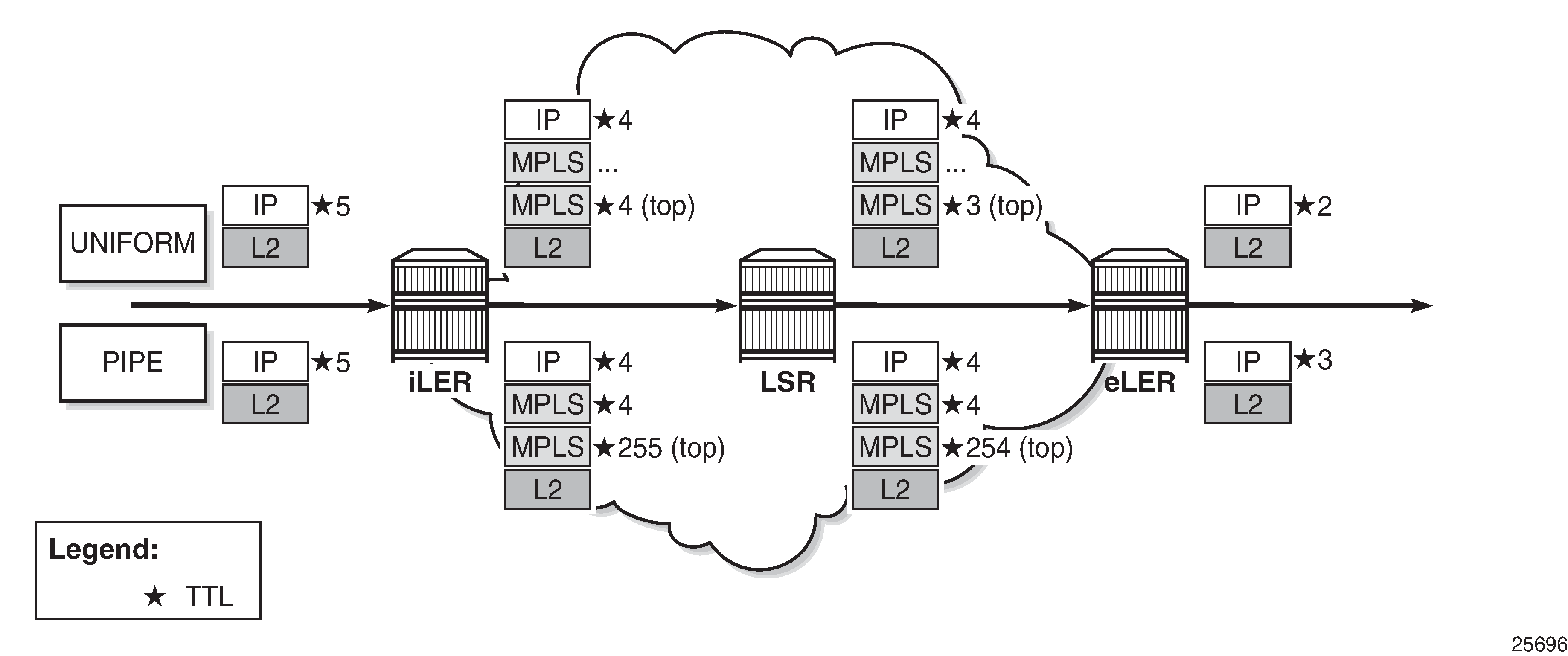
Independent of the mode, the iLER decrements the TTL in the IP header by one. The iLER adds service and transport MPLS headers.
In an L2 Virtual Private Network (VPN), the TTL in the IP header is kept intact.
In uniform mode, the iLER sets the TTL of every MPLS header to match the TTL in the IP header and every LSR decrements the MPLS TTLs. The IP header remains unchanged as long as the packet is in the MPLS tunnel. The eLER pops the MPLS labels and decrements the minimum TTL of the headers (which is the TTL in both MPLS headers) by one. This TTL is used in the IP header.
In pipe mode, the iLER sets the TTL of the top MPLS header to 255 and every LSR decrements that TTL by one. The eLER pops the MPLS labels and decrements the minimum TTL of the headers (which is the IP TTL) by one. This TTL is used in the IP header. There can be uncounted hops in pipe mode, because the LSRs are not counted.
The LERs can be in uniform mode and the LSRs in pipe mode, and the other way around.
The default use of TTL in SR OS is as follows:
Uniform mode for LSP shortcuts, ReSource reserVation Protocol (RSVP) shortcuts, Label Distribution Protocol (LDP) shortcuts, and Border Gateway Protocol (BGP) shortcuts.
Pipe mode for L2 and L3 VPN services, BGP labeled routes, IPv6 Provider Edge (6PE) router, and IPv6 on VPN to PE router (6VPE).
However, the use of TTL can be changed by configuration.
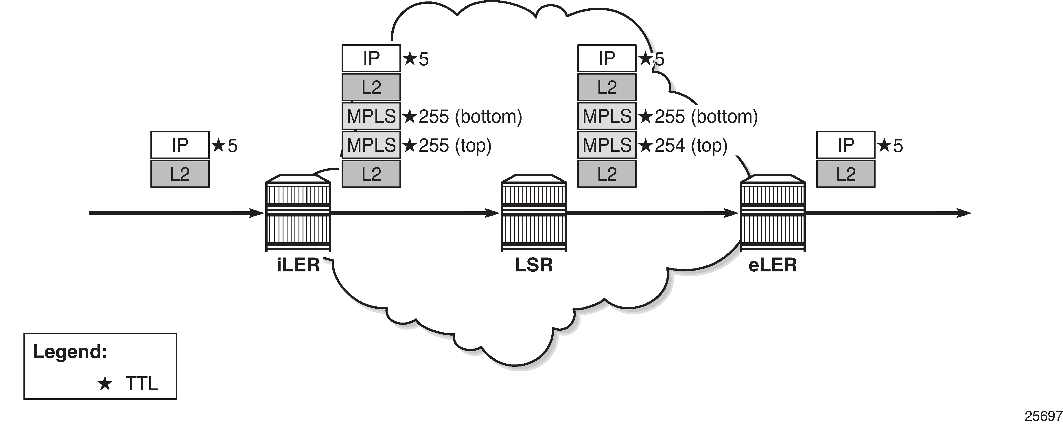
Use of TTL in an L2 VPN service in pipe mode shows the use of TTL for an L2 VPN service in pipe mode. The TTL in the IP header is preserved. There is no processing of the IP header for an L2 service. The TTL in the pushed MPLS headers is 255 and the TTL in the top MPLS header is decremented by one in the LSRs. The eLER pops the MPLS labels.
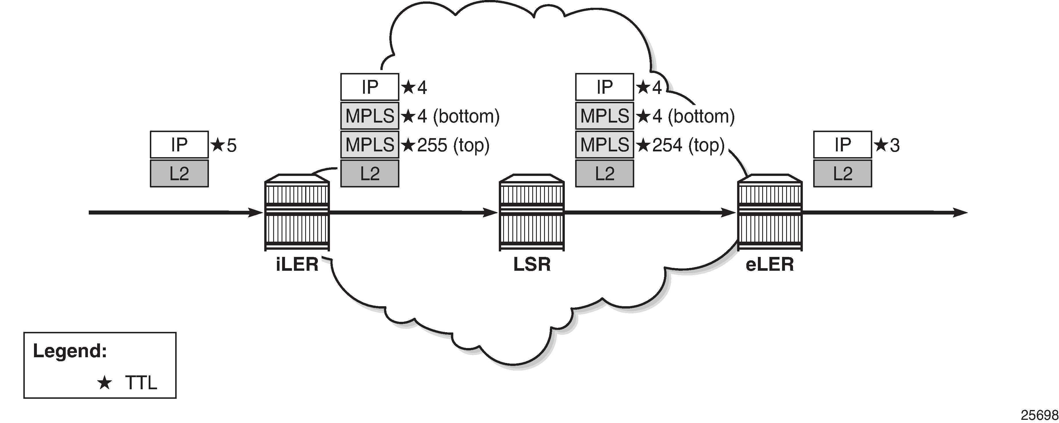
Use of TTL in an L3 VPN service in pipe mode shows the use of TTL for an L3 VPN service in pipe mode. The TTL in the IP header is decremented by the iLER and the eLER, but not by the LSRs. In pipe mode, the bottom MPLS header inherits the IP TTL after it has been decremented by the iLER. The transport MPLS header gets TTL 255 and this TTL is decremented by one at each LSR. The eLER takes the minimum of the TTL of the MPLS headers and the IP TTL and decrements that by one. This will match the IP TTL in the forwarded packet. The MPLS labels are popped. There are uncounted hops, because the LSRs are invisible in pipe mode.
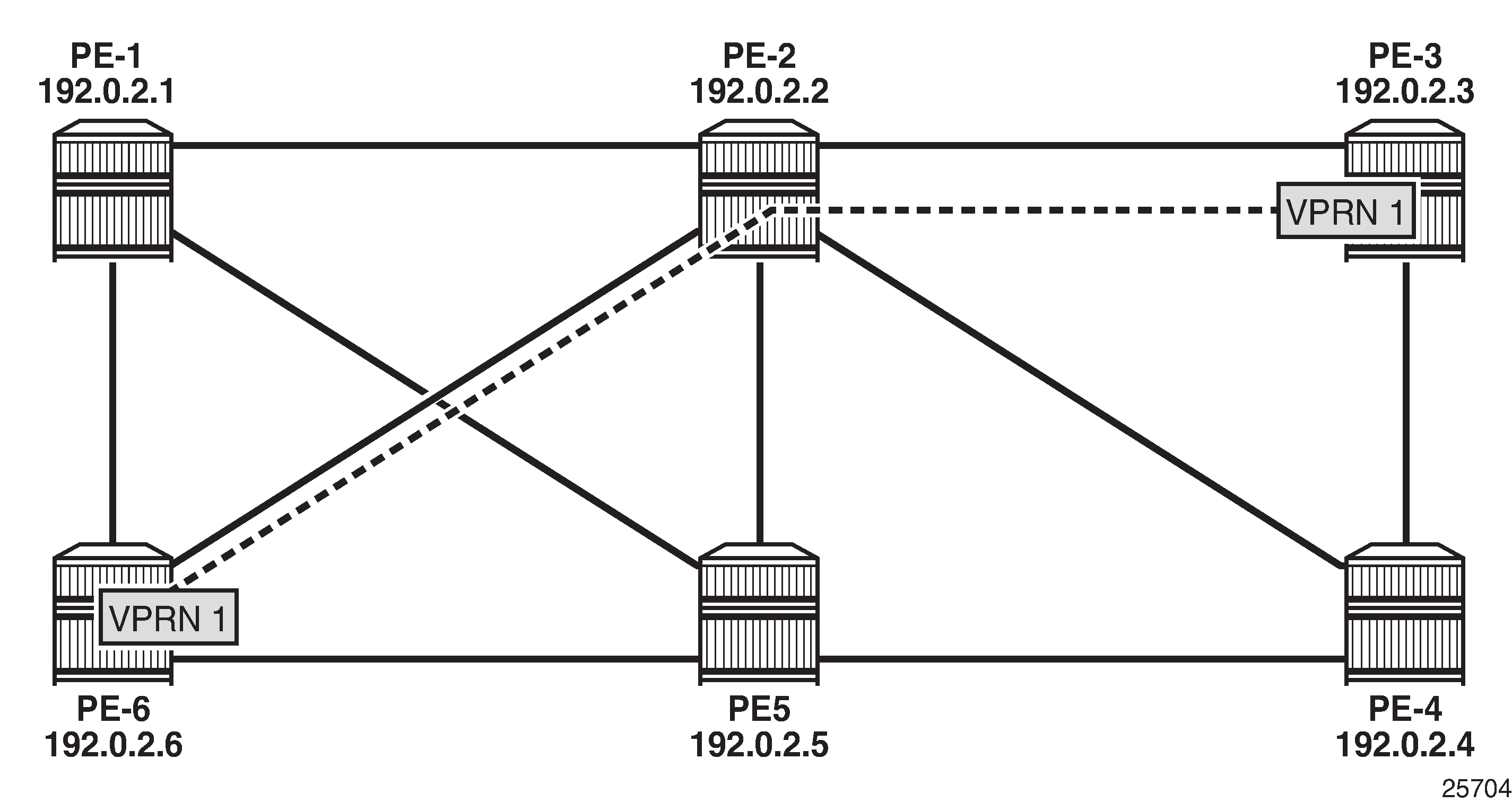
Tunneling of ICMP reply packets over MPLS LSPs provides the ability for a network operator or customer to trace the MPLS network hops in the path, for Virtual Private Routed Network (VPRN), 6PE/6VPE, and BGP labeled routes.
ICMP tunneling over an MPLS LSP
Tunneling of ICMP reply packets over an MPLS LSP shows the actions performed in iLER, LSR, and eLER, when tunneling ICMP messages over an MPLS LSP:
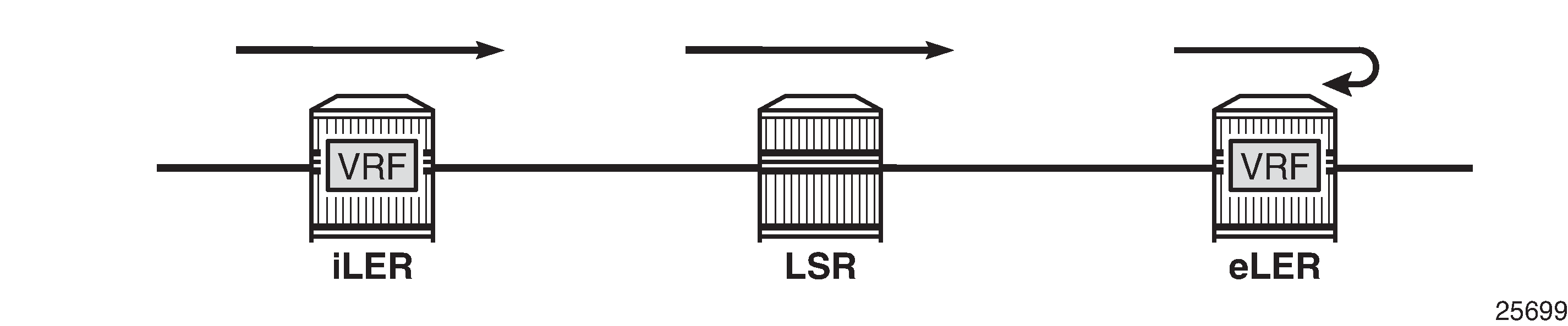
In the iLER, uniform mode is required within the VPRN service. The IP TTL is propagated in the MPLS TTL, both for in-transit and Control Processing Module (CPM) generated IP packets. In this example, it is assumed that a UDP traceroute message is forwarded with source IP address S1.
In all LSRs, ICMP tunneling is enabled globally on the system, according to RFC 3032, MPLS Label Stack Encoding. When the MPLS TTL expires in an LSR, the LSR generates an ICMP reply with code "Time exceeded" and destination IP address S1. However, the CPM sends this ICMP reply packet in the forward direction of the MPLS LSP tunnel that the packet arrived on. The ICMP reply packet is sent to the eLER, not to the iLER.
The eLER performs a lookup for the IP address S1 and sends the ICMP reply to S1 toward the iLER.
The lookup of the IP address S1 is in the Global Routing Table (GRT) for BGP shortcut, 6PE, and BGP labeled route prefixes.
The lookup of IP address S1 is in the Virtual Routing and Forwarding (VRF) table for VPRN and 6VPE prefixes.
TTL propagation
The TTL propagation can be configured in LERs and LSRs.
TTL propagation at the iLER
Different commands are used for TTL propagation in a VPRN versus BGP labeled routes. Pipe mode is enabled by default in either case.
TTL propagation in iLER for VPRN
The TTL propagation of VPN-IPv4 or VPN-IPv6 packets in a VPRN service can be enabled globally as follows:
A:PE-3# configure router ttl-propagate vprn-local
  - vprn-local <ttl-prop-type>

 <ttl-prop-type>      : none|all|vc-only - Default: vc-only

A:PE-3# configure router ttl-propagate vprn-transit
  - vprn-transit <ttl-prop-type>

 <ttl-prop-type>      : none|all|vc-only - Default: vc-only
There are three options for the propagation of TTL in the iLER of a VPRN:
none |
No IP TTL propagation to any MPLS header in the stack: the transport and the VC MPLS headers will have a value of 255. This is needed for correct operation of traceroute in an inter-AS option B VPRN. |
all |
Uniform mode: IP TTL is propagated to all MPLS headers in the stack. |
vc-only (default) |
Pipe mode: IP TTL is propagated to the VC header, but not to the transport headers in the stack. |
For more information about inter-AS option B, see chapter Rosen MVPN Inter-AS Option B.
In inter-AS option B, a traceroute for a VPN IP prefix issued from a Customer Edge (CE) router results in both ingress Autonomous System Boundary Router (ASBR) and egress ASBR not responding. The traceroute also misses a couple of hops if the target CE node is two or more hops away from the egress PE. The reason is that the VC label TTL inherits the decremented IP TTL at the ingress PE, but is decremented twice in the MPLS network whereas the IP TTL is only decremented at the ingress and the egress PE nodes. The option "none" for ttl-propagate makes the ASBRs transparent to the traceroute behavior and corrects the uncounted hop issue.
The global configuration can be overruled within each VPRN, as follows
A:PE-3# configure service vprn 1 ttl-propagate local
  - local <ttl-prop-type>

 <ttl-prop-type>      : none|all|vc-only|inherit - Default: inherit

A:PE-3# configure service vprn 1 ttl-propagate transit
  - transit <ttl-prop-type>

 <ttl-prop-type>      : none|all|vc-only|inherit - Default: inherit
TTL propagation in iLER for BGP labeled route
IPv4 and IPv6 packets are forwarded using BGP labeled routes in the GRT, as described in RFC 3107, Carrying Label Information in BGP-4. This also applies to 6PE. TTL propagation for RFC 3107 label routes can be configured as follows:
A:PE-3# configure router ttl-propagate label-route-local
  - label-route-local <ttl-prop-type>

 <ttl-prop-type>      : none|all - Default: none

A:PE-3# configure router ttl-propagate label-route-transit
  - label-route-transit <ttl-prop-type>

 <ttl-prop-type>      : none|all - Default: none
There are two options for TTL propagation in the iLER for BGP labeled routes:
none (default) |
Pipe mode: No TTL is propagated from the IP header to the MPLS headers in the transport MPLS stack. However, the IP TTL is propagated to the bottom header: the virtual circuit (VC) header |
all |
Uniform mode: TTL is propagated to all headers in the transport MPLS stack. |
If the BGP peer advertises the implicit-null label value for the BGP labeled route (in the case of a third-party implementation), the TTL propagation follows the configuration of the RSVP/LDP LSP shortcut that the BGP labeled route resolves to. This is not controlled by the preceding commands.
TTL propagation at the LSR
In a VPRN service, there is no TTL propagation to be configured in the LSRs.
TTL propagation in LSR for BGP labeled route
The IP TTL and VC TTL are not decremented by the LSRs. The TTL that is decremented is the minimum of the RSVP/LDP transport TTL and the BGP TTL.
The LSR determines the TTL using the following function:
TTL = MIN {incoming transport label stack TTL, incoming swapped/stitched label TTL}
The LSR decrements the TTL by one and writes it to the outgoing swapped/stitched BGP label.
This is always performed when an LSR is swapping or stitching a label at any stack depth.
The control plane indicates to the data plane whether a BGP labeled route is stitched or an LDP FEC is being stitched. The same node can perform stitching for one BGP labeled route and swapping for another one. See chapter LDP FEC to BGP Label Route Stitching for more information.
The LSR can propagate the decremented TTL to the outgoing transport label stack (if any) that is pushed on top of the BGP swapped/stitched label. This is configured as follows:
A:PE-2# configure router ttl-propagate lsr-label-route
  - lsr-label-route <ttl-prop-type>

 <ttl-prop-type>      : none|all - Default: none
There are two options for TTL propagation in the LSR:
none (default) |
No TTL propagation of the decremented TTL to the MPLS transport label stack. |
all |
TTL propagation of the decremented TTL to all LDP/RSVP transport labels. |
It is safe to not propagate the TTL to the transport label stack for an ASBR/Area Border Router (ABR)/data path Route Reflector (RR)/BGP-LDP stitching node. Not propagating the TTL provides isolation of the network domains downstream of the LSRs. Operations, Administration, and Maintenance (OAM) packets, such as traceroute and ping, sent in the context of a BGP labeled route or VPRN will not expire in LSR nodes within these domains.
A node performing pseudowire (PW) switching terminates the transport label stack in pipe mode; the node ignores the TTL of the incoming transport label stack and propagates the TTL of the VC label. The TTL of the new pushed transport label stack is always 255.
Some considerations on TTL propagation in LSR for BGP labeled routes
When an LSR stitches an LDP label to a BGP label, the decremented TTL of the stitched label can be propagated to the LDP/RSVP transport labels with the preceding configuration.
When an LSR stitches a BGP label to an LDP label, the decremented TTL of the stitched label is automatically propagated to the RSVP label if the outgoing LDP LSP is tunneled over RSVP.
When the LSR pops a BGP label and forwards the packet using an IGP route (IGP route is preferred over BGP labeled route), the LSR pushes an LDP label on the packet and the TTL behavior is the same as when an LSR stitches a BGP label to an LDP label.
In a Carrier Supporting Carrier (CSC) VPRN, the ingress CSC CE swaps an iBGP label for an eBGP label and the ingress CSC PE swaps the incoming eBGP label for a VPN-IPv4 label. The reverse operation is performed by the egress CSC PE and the egress CSC CE. In all cases, the decremented TTL of the swapped label is propagated to the LDP/RSVP transport labels.
SR OS does not support ASBR or data path RR functionality for labeled IPv6 routes in the global routing instance (6PE).
TTL propagation at the eLER
For packets received with a BGP labeled route and searched for in the GRT, the TTL of the forwarded IP packet is set to MIN{MPLS_TTL-1, IP_TTL-1}, where MPLS_TTL refers to the TTL in the outermost label in the popped stack. This is the same behavior as for LSP shortcuts.
For packets received in the context of VPRN, the TTL of the forwarded IP packet is set to MIN{MPLS_TTL-1, VC_TTL-1, IP_TTL-1}, where MPLS_TTL refers to the TTL in the outermost label in the popped stack and VC_TTL refers to the TTL in the VC label in the popped stack.
Some considerations on TTL propagation at the eLER
When a packet is received in one VPRN instance and is redirected using policy-based routing to be forwarded in another VPRN instance, the TTL is governed by the configuration of the outgoing VPRN instance.
When a packet is received in a vprn context but is searched for in the GRT (GRT leaking configured), the behavior of the TTL propagation is governed by:
the BGP labeled route configuration when the matching route is an RFC 3107 label route or a 6PE route
the LSP shortcut configuration when the matching route is an RSVP or LDP shortcut (default uniform mode)
For shortcuts, uniform mode is default. Pipe mode can be configured as follows:
# on eLER PE-6:
configure
    router
        ldp
            no shortcut-local-ttl-propagate
            no shortcut-transit-ttl-propagate
        exit
        mpls
            no shortcut-local-ttl-propagate
            no shortcut-transit-ttl-propagate
        exit
Enabling ICMP tunneling on LSRs
For all scenarios (VPRN and BGP labeled routes), ICMP tunneling needs to be enabled on all LSRs, as follows:
# on all LSRs:
configure
    router
        icmp-tunneling
The LSR will generate the ICMP reply packet of type 11 - "Time exceeded", with source IP address set to a local address of the LSR node and appending the IP header and leading octets of the original datagram. The LSR does not perform a lookup for the destination IP address of the ICMP reply packet, which is the source IP address of the sender of the label TTL expiry packet. The CPM injects the ICMP reply packet in the forward direction toward the eLER. The TTL of pushed labels is 255.
There is no need to enable ICMP tunneling on the eLER. The eLER performs a user packet lookup in the data path in the VRF table or GRT and forwards the ICMP reply packet to the destination. If the eLER does not have a route to the destination, the packet is dropped.
RFC 4950, ICMP Extensions for Multiprotocol Label Switching, defines an extension object (MPLS label stack object) that allows LSRs to include label stack information to ICMP messages; see MPLS label stack object:
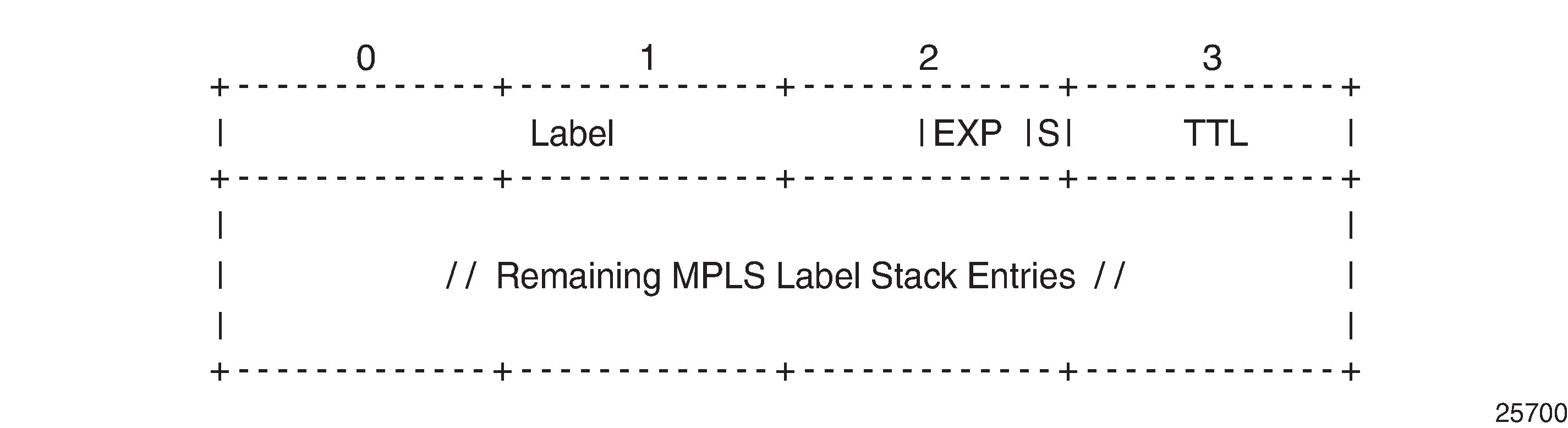
The MPLS label stack object is applicable for ICMPv4 and ICMPv6. The MPLS label stack contains the MPLS shim header: label, experimental bits for Type of Service (ToS), S-bit indicating the bottom of the stack, and TTL. The object can be appended to the ICMP Time Exceeded and ICMP Destination Unreachable messages. The LSR that sends the ICMP reply message will not change the MPLS label stack.
RFC 4884, Extended ICMP to Support Multi-Part Messages, defines the ICMP extension header; see ICMP extension header:
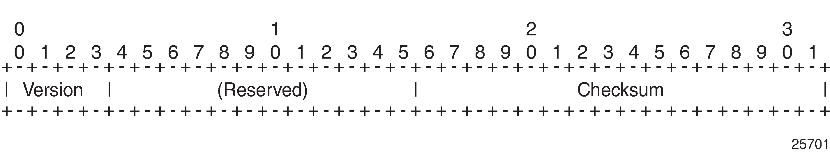
The version of the ICMP extension header is 2. The twelve reserved bits must be set to 0.
An extension object contains 32-bit words, representing an object header and payload, as defined in RFC 4884; see ICMP extension object: object header and payload:
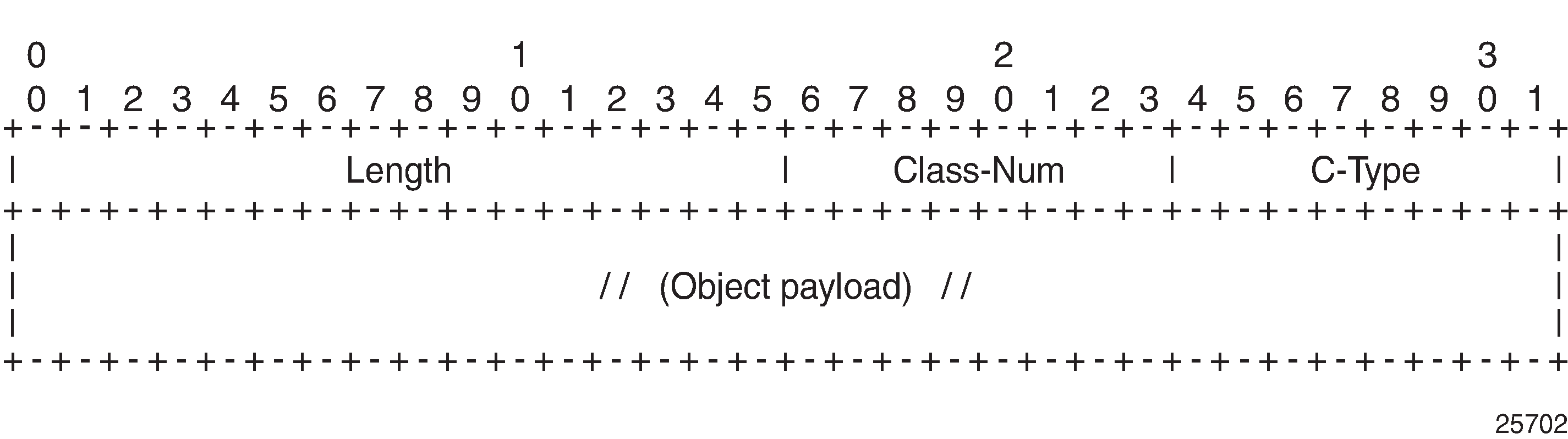
The length of the object is the length of the header (4 octets) plus the length of the object payload: 4 octets per LSR. The class number identifies the object class; in this case, object class 1 for MPLS label stack class. The C-type defines the object subtype; in this case, the subtype is 1 for an incoming MPLS label stack.
Backward compatibility is guaranteed between the ICMP message with extension header, the ICMP messages without extension header, and the ICMP message with a non-compliant extension header.
Effect of ICMP tunneling on OAM
ICMP tunneling over MPLS LSPs affects the behavior of some CPM originated OAM packets that are forwarded within a vprn context.
ICMP ping and UDP traceroute are sent according to the TTL propagation configured in the vprn context.
VPRN ping and VPR traceroute are not affected.
OAM packets forwarded over a BGP labeled route follow the TTL configuration of the iLER.
ICMP tunneling behavior at an LSR only applies to UDP traceroute packets. Other OAM packets expiring at the LSR, such as ICMP ping, VPRN ping, VPRN trace, LSP ping, and LSP trace, follow their specific procedures or are silently dropped.
Configuration
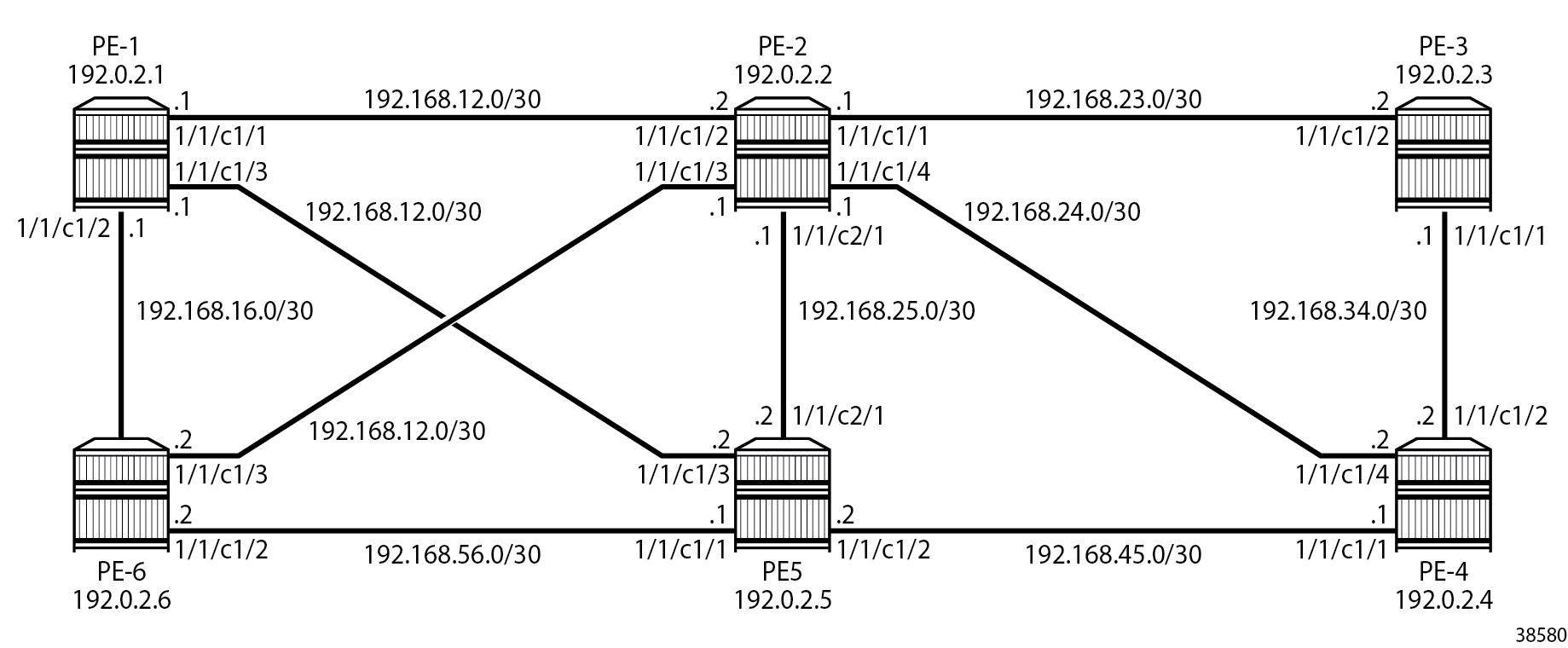
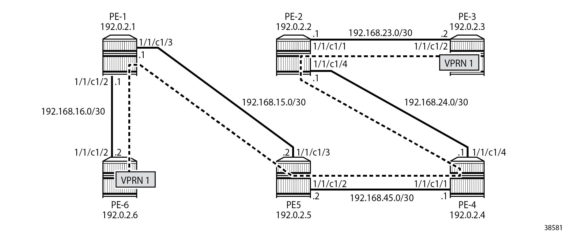
Example configuration shows the example configuration, which has six 7750 SRs:
Initial configuration
The nodes have the following initial configuration:
Cards, MDAs, ports
Router interfaces.
# on PE-3:
configure
    router
        interface "int-PE-3-PE-2"
            address 192.168.23.2/30
            port 1/1/c1/2
        exit
        interface "int-PE-3-PE-4"
            address 192.168.34.1/30
            port 1/1/c1/1
        exit
        interface "system"
            address 192.0.2.3/32
        exit
IGP: OSPF (alternatively, any IGP could have been used).
# on PE-3:
configure
    router
        ospf
            area 0
                interface "system"
                exit
                interface "int-PE-3-PE-2"
                    interface-type point-to-point
                exit
                interface "int-PE-3-PE-4"
                    interface-type point-to-point
                exit
            exit
            no shutdown
Link LDP.
# on PE-3:
configure
    router
        ldp
            interface-parameters
                interface "int-PE-3-PE-2" dual-stack
                    ipv4
                        no shutdown
                    exit
                    no shutdown
                exit
                interface "int-PE-3-PE-4" dual-stack
                    ipv4
                        no shutdown
                    exit
                    no shutdown
                exit
Configure VPRN
A VPRN service is configured on PE-3 and PE-6. The routes are exchanged via BGP. BGP is configured on all nodes with PE-2 as route reflector (RR).
# on PE-1, PE-3, PE-4, PE-5, and PE-6:
configure
    router
        autonomous-system 64496
        bgp
            group "internal"
                family vpn-ipv4
                peer-as 64496
                neighbor 192.0.2.2
                exit
            exit
            no shutdown
The configuration on RR PE-2 is as follows:
# on PE-2:
configure
    router
        autonomous-system 64496
        bgp
            cluster 1.1.1.1
            group "internal"
                family vpn-ipv4
                peer-as 64496
                neighbor 192.0.2.1
                exit
                neighbor 192.0.2.3
                exit
                neighbor 192.0.2.4
                exit
                neighbor 192.0.2.5
                exit
                neighbor 192.0.2.6
                exit
            exit
            no shutdown
Import and export policies are configured on PE-3 and PE-6, as follows:
# on PE-3 and PE-6:
configure
    router
        policy-options
            begin
            community "VPN1"
                members "target:64496:1"
            exit
            policy-statement "VPN1-export"
                entry 10
                    from
                        protocol direct
                    exit
                    to
                        protocol bgp-vpn
                    exit
                    action accept
                        community add "VPN1"
                    exit
                exit
            exit
            policy-statement "VPN1-import"
                entry 10
                    from
                        protocol bgp-vpn
                        community "VPN1"
                    exit
                    action accept
                    exit
                exit
            exit
            commit
VPRN 1 is configured on PE-3 and PE-6, as follows:
# on PE-3:
configure
    service
        vprn 1 name "1" customer 1 create
            interface "loopback1" create
                address 192.0.1.3/32
                loopback
            exit
            bgp-ipvpn
                mpls
                    auto-bind-tunnel
                        resolution-filter
                            ldp
                        exit
                        resolution filter
                    exit
                    route-distinguisher 64496:13
                    vrf-import "VPN1-import"
                    vrf-export "VPN1-export"
                    no shutdown
                exit
            exit
            no shutdown
The configuration on PE-6 is similar, with route-distinguisher 64496:16 and loopback address 192.0.1.6/32.
Default TTL handling in VPRN
The default configuration for TTL propagation on the iLER corresponds to pipe mode, as follows:
# on PE-3:
configure
    router
        ttl-propagate
            info detail
*A:PE-3>config>router>ttl-propagate#             info detail
----------------------------------------------
            label-route-local none
            label-route-transit none
            lsr-label-route none
            vprn-local vc-only
            vprn-transit vc-only
----------------------------------------------
By default, no ICMP tunneling is enabled in the LSRs, which implies that no ICMP "Time exceeded" messages will be tunneled by the LSR to the eLER. A traceroute message sent in VPRN 1 from PE-3 to the loopback address in VPRN 1 on PE-6 shows that the loopback address is the next hop. There are no intermediate hops detected.
*A:PE-3# traceroute router 1 192.0.1.6
traceroute to 192.0.1.6, 30 hops max, 40 byte packets
  1  192.0.1.6 (192.0.1.6)    1.82 ms  1.74 ms  1.69 ms
Tunnel from iLER PE-3 to eLER PE-6 via LSR PE-2 shows the tunnel from iLER PE-3 to eLER PE-6:
For comparison, a traceroute in the base router toward the system address of PE-6 shows PE-2 as intermediate hop, as follows:
*A:PE-3# traceroute 192.0.2.6
traceroute to 192.0.2.6, 30 hops max, 40 byte packets
  1  192.168.23.1 (192.168.23.1)    0.911 ms  1.02 ms  1.01 ms
  2  192.0.2.6 (192.0.2.6)    1.59 ms  1.40 ms  1.44 ms
Uniform mode in iLER and ICMP tunneling in LSR
In the iLER PE-3, uniform mode is enabled for local VPRNs, as follows:
# on iLER PE-3:
configure
    service
        vprn 1
            ttl-propagate
                local all
This is a specific configuration for VPRN 1 that overrules the global configuration. By default, it is set to inherit the global configuration. By default, the global configuration is pipe mode.
This TTL propagation is only configured on PE-3, not on PE-6. This implies that traceroute messages from the VPRN in PE-3 will have TTL propagation to all MPLS labels (uniform mode), while traceroute messages from the VPRN in PE-6 will have pipe mode.
In the LSR PE-2, ICMP tunneling is enabled, as follows:
# on LSR PE-2:
configure
    router
        icmp-tunneling
A UDP traceroute is sent from VPRN 1 on PE-3 to the loopback address in VPRN 1 on PE-6. A message with TTL 1 is sent first. The IP TTL and VC TTL are not decremented by the LSR PE-2. Only the LDP TTL is decremented, so this message times out on the LSR PE-2, which tunnels the ICMP Time Exceeded reply with destination address 192.0.1.3 toward eLER PE-6. The eLER looks up the prefix 192.0.1.3 in the VRF table and sends the ICMP Time Exceeded reply toward VPRN 1 in PE-3. Three UDP traceroute messages with TTL 1 are sent. Then, UDP traceroute messages with TTL 2 are sent. They reach the destination PE-6 before time-out.
UDP traceroute in VPRN with iLER in uniform mode shows the TTLs in the UDP traceroute messages:
In the following output, there is only an MPLS label stack object when TTL expires in the LSR, because ICMP tunneling is occurring. The MPLS label stack object is not used by the eLER. The LSR where ICMP tunneling occurs adds an MPLS label stack object to the ICMP reply message. The MPLS label stack object contains information about the MPLS labels (VC label and LDP transport label) in the stack: MPLS labels, experimental bits for ToS, and TTL. S indicates the bottom of the label stack. In the detailed output of the traceroute command, the MPLS label stack information is shown for the echo requests that timed out in the LSR:
*A:PE-3# traceroute router 1 192.0.1.6 detail
traceroute to 192.0.1.6, 30 hops max, 40 byte packets
  1   1  192.168.26.1  (192.168.26.1)  1.67 ms
         returned MPLS Label Stack Object
             entry  1:  MPLS Label =  524282, Exp = 7, TTL =   1, S = 0
             entry  2:  MPLS Label =  524281, Exp = 7, TTL =   1, S = 1
  1   2  192.168.26.1  (192.168.26.1)  1.60 ms
         returned MPLS Label Stack Object
             entry  1:  MPLS Label =  524282, Exp = 7, TTL =   1, S = 0
             entry  2:  MPLS Label =  524281, Exp = 7, TTL =   1, S = 1
  1   3  192.168.26.1  (192.168.26.1)  1.58 ms
         returned MPLS Label Stack Object
             entry  1:  MPLS Label =  524282, Exp = 7, TTL =   1, S = 0
             entry  2:  MPLS Label =  524281, Exp = 7, TTL =   1, S = 1
  2   1  192.0.1.6  (192.0.1.6)  1.58 ms
  2   2  192.0.1.6  (192.0.1.6)  1.64 ms
  2   3  192.0.1.6  (192.0.1.6)  1.63 ms
The top label or transport label 524282 is the LDP label pushed by PE-3:
*A:PE-3# show router ldp bindings active prefixes prefix 192.0.2.6/32

===============================================================================
LDP Bindings (IPv4 LSR ID 192.0.2.3)
             (IPv6 LSR ID ::)
===============================================================================
Label Status:
        U - Label In Use, N - Label Not In Use, W - Label Withdrawn
        WP - Label Withdraw Pending, BU - Alternate For Fast Re-Route
        e - Label ELC
FEC Flags:
        LF - Lower FEC, UF - Upper FEC, M - Community Mismatch,
        BA - ASBR Backup FEC
        (S) - Static           (M) - Multi-homed Secondary Support
        (B) - BGP Next Hop     (BU) - Alternate Next-hop for Fast Re-Route
        (I) - SR-ISIS Next Hop (O) - SR-OSPF Next Hop
        (C) - FEC resolved with class-based-forwarding
===============================================================================
LDP IPv4 Prefix Bindings (Active)
===============================================================================
Prefix                                      Op
IngLbl                                      EgrLbl
EgrNextHop                                  EgrIf/LspId
-------------------------------------------------------------------------------
192.0.2.6/32                                Push
  --                                        524282
192.168.23.1                                1/1/c1/2

192.0.2.6/32                                Swap
524282                                      524282
192.168.23.1                                1/1/c1/2

-------------------------------------------------------------------------------
No. of IPv4 Prefix Active Bindings: 2
===============================================================================
The bottom label or service label 524281 is the BGP label, which remains the same end-to-end:
*A:PE-3# show router bgp routes vpn-ipv4
===============================================================================
 BGP Router ID:192.0.2.3        AS:64496       Local AS:64496
===============================================================================
 Legend -
 Status codes  : u - used, s - suppressed, h - history, d - decayed, * - valid
                 l - leaked, x - stale, > - best, b - backup, p - purge
 Origin codes  : i - IGP, e - EGP, ? - incomplete

===============================================================================
BGP VPN-IPv4 Routes
===============================================================================
Flag  Network                                            LocalPref   MED
      Nexthop (Router)                                   Path-Id     IGP Cost
      As-Path                                                        Label
-------------------------------------------------------------------------------
i     64496:13:192.0.1.3/32                              100         None
      192.0.2.3                                          None        0
      No As-Path                                                     524281
u*>i  64496:16:192.0.1.6/32                              100         None
      192.0.2.6                                          None        20
      No As-Path                                                     524281
-------------------------------------------------------------------------------
Routes : 2
===============================================================================
When the iLER is configured in pipe mode (vc-only) or if there is no TTL propagation to any MPLS label (none), the output of the traceroute detail command does not contain the MPLS label stack object information. In pipe mode, the IP TTL is propagated to the VC header, but not to the LDP header. When the TTL propagation is none, the IP TTL is not propagated to VC or LDP. The LSRs are invisible and there will be missing hops.
# on PE-3:
configure
    service
        vprn 1
            ttl-propagate
                local vc-only
*A:PE-3# traceroute router 1 192.0.1.6 detail
traceroute to 192.0.1.6, 30 hops max, 40 byte packets
  1   1  192.0.1.6  (192.0.1.6)  1.68 ms
  1   2  192.0.1.6  (192.0.1.6)  1.67 ms
  1   3  192.0.1.6  (192.0.1.6)  1.66 ms
The reason is that the TTL of the LDP header is 255 at the iLER and it is decremented by one in every LSR. The UDP traceroute message will not time out on the LSR PE-2. The TTL of the VC header is not decremented in the LSR. When the traceroute message does not time out in PE-2, the hop PE-2 is invisible. In a similar way, the traceroute messages will not time out in the LSR when no TTLs are propagated to any MPLS header. UDP traceroute in VPRN without TTL propagation to LDP shows the TTLs in both cases:
The TTL propagation is restored to uniform mode in the iLER as follows:
# on PE-3:
configure
    service
        vprn 1
            ttl-propagate
                local all
Uniform mode in iLER and ICMP tunneling in multiple LSRs
After disabling some ports in the nodes, the tunnel from iLER PE-3 to PE-6 has four intermediate hops (LSRs) instead of one, as shown in Tunnel from iLER PE-3 to eLER PE-6 with multiple LSRs:
# on PE-2:
configure port 1/1/c1/2 shutdown
configure port 1/1/c1/3 shutdown
configure port 1/1/c2/1 shutdown

# on PE-3:
configure port 1/1/c1/1 shutdown

# on PE-5:
configure port 1/1/c1/1 shutdown
TTL propagation on the iLER PE-3 is in uniform mode. ICMP tunneling needs to be enabled on all LSRs, as follows:
# on all LSRs:
configure
    router
        icmp-tunneling
UDP traceroute messages are sent from VPRN 1 on iLER PE-3 to VPRN 1 on PE-6, as shown in UDP traceroute with iLER in uniform mode:
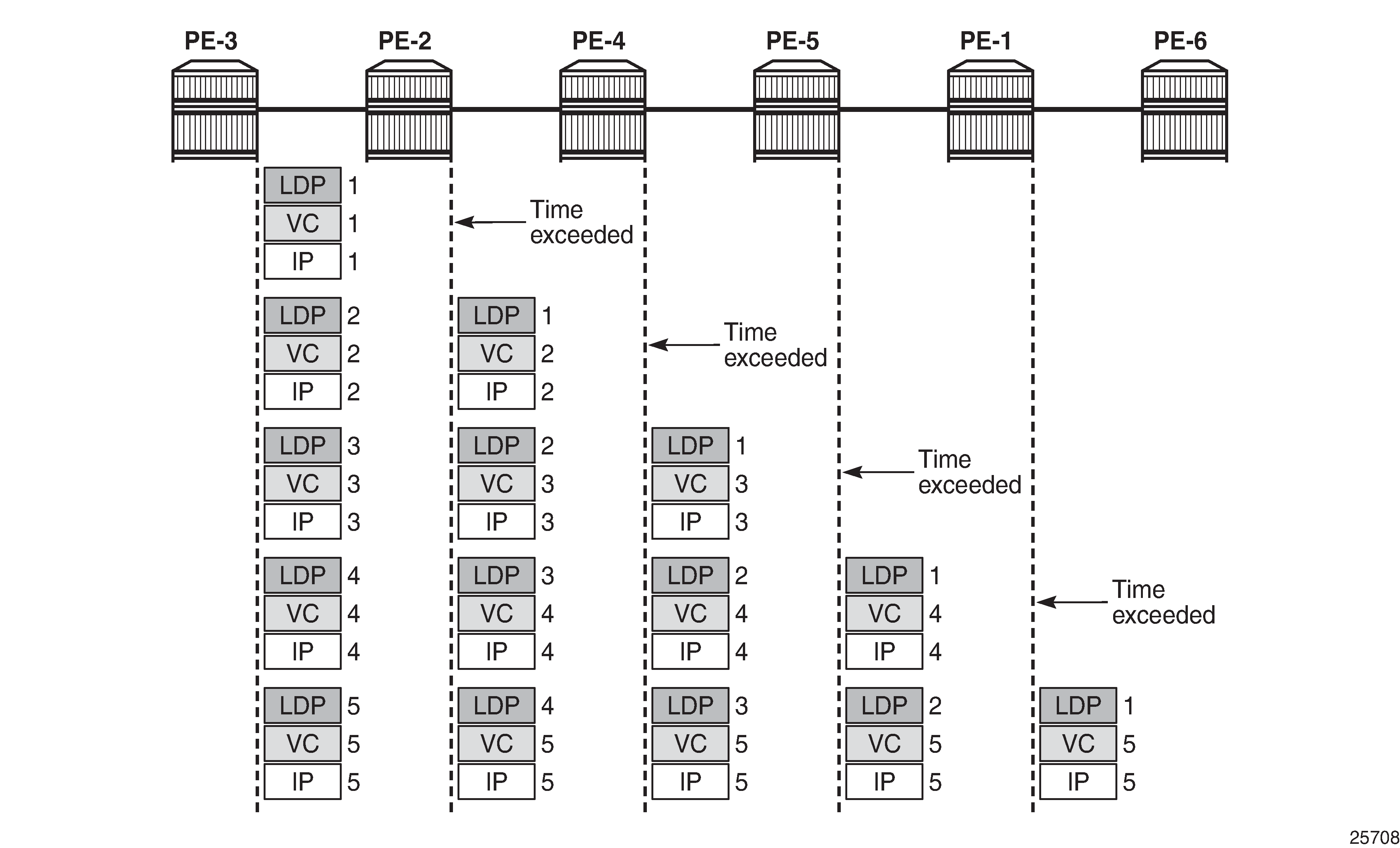
The detailed output of the traceroute command shows the MPLS label stack object information as added by the LSR where the ICMP Time Exceeded message was tunneled. For brevity, only the first of the three messages from each intermediate node is shown.
*A:PE-3# traceroute router 1 192.0.1.6 detail
traceroute to 192.0.1.6, 30 hops max, 40 byte packets
  1   1  192.168.24.1  (192.168.24.1)  3.17 ms
         returned MPLS Label Stack Object
             entry  1:  MPLS Label =  524279, Exp = 7, TTL =   1, S = 0
             entry  2:  MPLS Label =  524281, Exp = 7, TTL =   1, S = 1
---snip---
  2   1  192.168.45.1  (192.168.45.1)  3.76 ms
         returned MPLS Label Stack Object
             entry  1:  MPLS Label =  524281, Exp = 7, TTL =   1, S = 0
             entry  2:  MPLS Label =  524281, Exp = 7, TTL =   2, S = 1
---snip---
  3   1  192.168.15.2  (192.168.15.2)  2.91 ms
         returned MPLS Label Stack Object
             entry  1:  MPLS Label =  524282, Exp = 7, TTL =   1, S = 0
             entry  2:  MPLS Label =  524281, Exp = 7, TTL =   3, S = 1
---snip---
  4   1  192.168.16.1  (192.168.16.1)  2.77 ms
         returned MPLS Label Stack Object
             entry  1:  MPLS Label =  524282, Exp = 7, TTL =   1, S = 0
             entry  2:  MPLS Label =  524281, Exp = 7, TTL =   4, S = 1
---snip---
  5   1  192.0.1.6  (192.0.1.6)  2.96 ms
---snip---
The TTL for the bottom MPLS header (BGP) is not decremented in each hop; only the TTL for the transport MPLS header (LDP) is decremented. The bottom label or BGP label of 524281 is not changed end-to-end. The LDP transport label for the different nodes is as follows.
For iLER PE-3, the LDP transport label for traffic toward PE-6 is 524279:
*A:PE-3# show router ldp bindings active prefixes prefix 192.0.2.6/32

===============================================================================
LDP Bindings (IPv4 LSR ID 192.0.2.3)
             (IPv6 LSR ID ::)
===============================================================================
---snip---
===============================================================================
LDP IPv4 Prefix Bindings (Active)
===============================================================================
Prefix                                      Op
IngLbl                                      EgrLbl
EgrNextHop                                  EgrIf/LspId
-------------------------------------------------------------------------------
192.0.2.6/32                                Push
  --                                        524279
192.168.23.1                                1/1/c1/2

192.0.2.6/32                                Swap
524278                                      524279
192.168.23.1                                1/1/c1/2

-------------------------------------------------------------------------------
No. of IPv4 Prefix Active Bindings: 2
===============================================================================
For LSR PE-2, the LDP transport label toward PE-6 is 524281:
*A:PE-2# show router ldp bindings active prefixes prefix 192.0.2.6/32

===============================================================================
LDP Bindings (IPv4 LSR ID 192.0.2.2)
             (IPv6 LSR ID ::)
===============================================================================
---snip---
===============================================================================
LDP IPv4 Prefix Bindings (Active)
===============================================================================
Prefix                                      Op
IngLbl                                      EgrLbl
EgrNextHop                                  EgrIf/LspId
-------------------------------------------------------------------------------
192.0.2.6/32                                Push
  --                                        524281
192.168.24.2                                1/1/c1/4

192.0.2.6/32                                Swap
524279                                      524281
192.168.24.2                                1/1/c1/4

-------------------------------------------------------------------------------
No. of IPv4 Prefix Active Bindings: 2
===============================================================================
For LSR PE-4, the LDP transport label toward PE-6 is 524282:
*A:PE-4# show router ldp bindings active prefixes prefix 192.0.2.6/32

===============================================================================
LDP Bindings (IPv4 LSR ID 192.0.2.4)
             (IPv6 LSR ID ::)
===============================================================================
---snip---
===============================================================================
LDP IPv4 Prefix Bindings (Active)
===============================================================================
Prefix                                      Op
IngLbl                                      EgrLbl
EgrNextHop                                  EgrIf/LspId
-------------------------------------------------------------------------------
192.0.2.6/32                                Push
  --                                        524282
192.168.45.2                                1/1/c1/1

192.0.2.6/32                                Swap
524281                                      524282
192.168.45.2                                1/1/c1/1

-------------------------------------------------------------------------------
No. of IPv4 Prefix Active Bindings: 2
===============================================================================
For LSR PE-5, the LDP transport label toward PE-6 is 524282:
*A:PE-5# show router ldp bindings active prefixes prefix 192.0.2.6/32

===============================================================================
LDP Bindings (IPv4 LSR ID 192.0.2.5)
             (IPv6 LSR ID ::)
===============================================================================
---snip---
===============================================================================
LDP IPv4 Prefix Bindings (Active)
===============================================================================
Prefix                                      Op
IngLbl                                      EgrLbl
EgrNextHop                                  EgrIf/LspId
-------------------------------------------------------------------------------
192.0.2.6/32                                Push
  --                                        524282
192.168.15.1                                1/1/c1/3

192.0.2.6/32                                Swap
524282                                      524282
192.168.15.1                                1/1/c1/3

-------------------------------------------------------------------------------
No. of IPv4 Prefix Active Bindings: 2
===============================================================================
For LSR PE-1, the LDP transport label toward PE-6 is 524287, but this label will not be present in the traceroute detailed output, because this message cannot time out on an LSR where ICMP tunneling takes place:
*A:PE-1# show router ldp bindings active prefixes prefix 192.0.2.6/32

===============================================================================
LDP Bindings (IPv4 LSR ID 192.0.2.1)
             (IPv6 LSR ID ::)
===============================================================================
---snip---
===============================================================================
LDP IPv4 Prefix Bindings (Active)
===============================================================================
Prefix                                      Op
IngLbl                                      EgrLbl
EgrNextHop                                  EgrIf/LspId
-------------------------------------------------------------------------------
192.0.2.6/32                                Push
  --                                        524287
192.168.16.2                                1/1/c1/2

192.0.2.6/32                                Swap
524282                                      524287
192.168.16.2                                1/1/c1/2

-------------------------------------------------------------------------------
No. of IPv4 Prefix Active Bindings: 2
===============================================================================
Conclusion
Tunneling of ICMP reply messages over MPLS LSPs provides the ability to trace the hops in an MPLS tunnel. This mechanism applies to VPRN, 6PE/6VPE, and BGP labeled routes.
ICMP tunneling at an LSR applies to UDP traceroute packets that time out at the LSR. The ICMP Time Exceeded message is tunneled by the LSR toward the eLER and the eLER routes the packet to the sender of the traceroute message.