MPLS Transport Profile
This chapter provides information about multi-protocol label switching transport profile (MPLS-TP).
Topics in this chapter include:
Applicability
This chapter is applicable to SR OS and was initially written for SR OS Release 12.0.R2. The CLI in the current edition corresponds to SR OS Release 23.3.R3.
The reader should be familiar with the configuration of IP/MPLS and virtual leased line (VLL) services in SR OS.
MPLS-TP was first introduced in SR OS Release 11.0.R4 and further enhancements were added in subsequent SR OS releases.
Overview
MPLS-TP is intended to allow MPLS to be operated in a manner similar to existing transport technologies, with static configuration of transport paths (particularly with no requirement for a dynamic control plane), proactive in-band and on-demand operations, administration, and maintenance (OAM), and protection mechanisms that do not rely on a control plane (for example, resource reservation protocol with traffic engineering (RSVP-TE)) to operate. SR OS routers can operate both as a label edge router (LER) and label switching router (LSR) for MPLS-TP LSPs, and as a terminating provider edge (T-PE) and switching provider edge (S-PE) for pseudowires (PWs) with MPLS-TP OAM. The SR OS router can therefore act as a node within an MPLS-TP network, or as a gateway between MPLS-TP and IP/MPLS domains.
MPLS can provide a network layer with packet transport services. In some operational environments, it is desirable that the operation and maintenance of such an MPLS based packet transport network follows the operational models typically used in traditional optical transport networks (for example with SONET, SDH) while providing additional OAM, survivability, and other maintenance functions targeted at that environment.
MPLS-TP defines a profile of MPLS targeted at transport applications. This profile defines specific MPLS characteristics and extensions required to meet the transport requirements, while retaining compliance with the standard IETF MPLS architecture and label switching paradigm. The basic architecture and requirements for MPLS-TP are described by the IETF in RFC 5654, RFC 5921, and RFC 5960, in order to meet two objectives:
To enable MPLS to be deployed in a transport network and operated in a manner similar to existing transport technologies.
To enable MPLS to support packet transport services with a similar degree of predictability to that found in existing transport networks.
In order to meet these objectives, MPLS-TP has a number of high-level characteristics:
MPLS-TP, including resilience and protection, operates in the absence of an IP control plane and IP. MPLS-TP does not modify the MPLS forwarding architecture, which is based on existing pseudowire and LSP constructs. Point-to-point LSPs may be unidirectional or bi-directional. Bi-directional LSPs must be congruent (i.e. co-routed and follow the same path in each direction) and are the only supported type on SR OS. MPLS-TP is only supported on static LSPs and pseudowires (PWs). Also, there is no LSP merging.
LSP and pseudowire monitoring is achieved using in-band OAM and does not rely on control plane or IP routing functions to determine the health of a path, for example, LDP hello failures do not trigger protection.
The system supports MPLS-TP on LSPs and PWs with static labels. MPLS-TP is not supported on dynamically signaled LSPs and PWs, although switching a static MPLS-TP PW to a targeted LDP (T-LDP) signaled PW is supported. MPLS-TP is supported for Epipe, Apipe, and Cpipe VLLs, and Epipe spoke SDP termination on IES, VPRN, and VPLS. Static PWs may use SDPs in addition to static MPLS-TP LSPs or RSVP-TE LSPs.
The following MPLS-TP OAM and protection mechanisms defined by the IETF are supported:
MPLS-TP generic associated channel for LSPs and PWs (RFC 5586)
MPLS-TP identifiers (RFC 6370)
Proactive continuity check (CC), connectivity verification (CV), and remote defect indicator (RDI) using bi-directional forwarding detection (BFD) for LSPs (RFC 6428)
On-demand CV for LSPs and PWs using LSP ping and LSP trace (RFC 6426)
1-for-1 linear protection for LSPs (RFC 6378)
Static PW status signaling (RFC 6478)
The system can play the role of an LER and an LSR for static MPLS-TP LSPs, and a PE/T-PE and an S-PE for static MPLS-TP PWs. It can also act as an S-PE for MPLS-TP segments between an MPLS network that strictly follows the transport profile and an MPLS network that supports both MPLS-TP and dynamic IP/MPLS.
Configuration
This section details the configuration steps for some simple MPLS-TP examples.
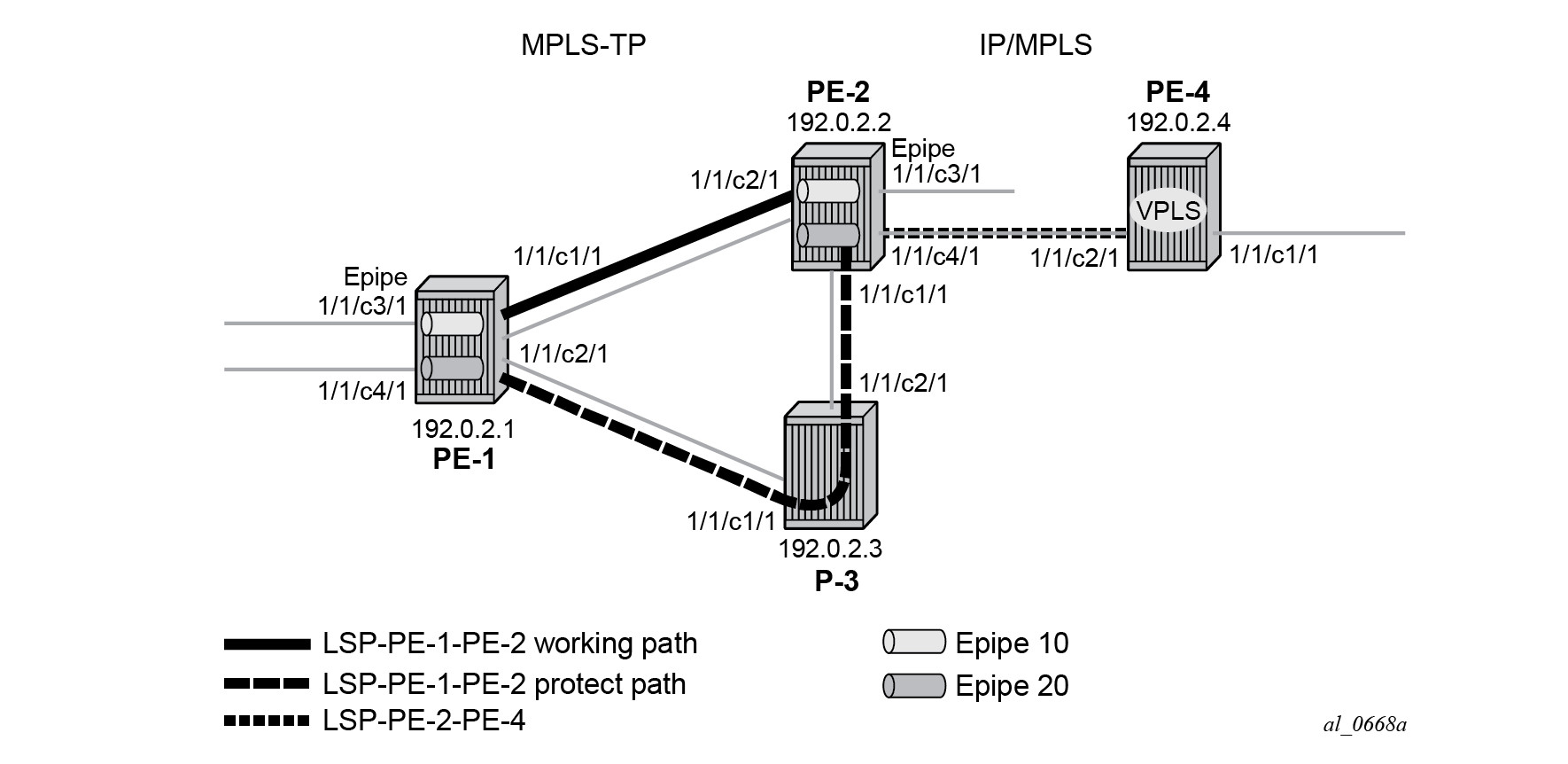
MPLS-TP example network showing LSPs shows the example topology. It consists of four nodes and two Epipe VLL services. One service is used to transport traffic across a network domain consisting of only static MPLS-TP LSPs (Epipe 10) from PE-1 to PE-2. The other Epipe (Epipe 20) is used to transport traffic from PE-1 in the MPLS-TP domain to a VPLS service on PE-4 in an IP/MPLS domain. A static MPLS-TP LSP exists between PE-1 and PE-2, while a dynamic RSVP-TE LSP exists between PE-2 and PE-4.
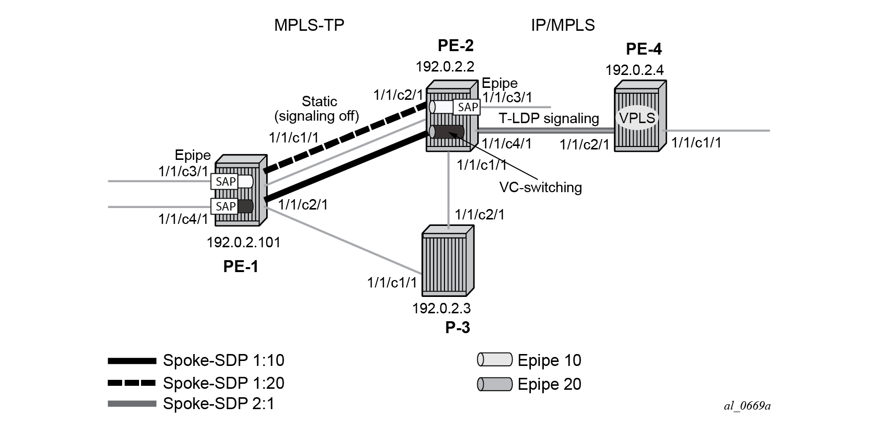
MPLS-TP example network showing services detail shows further details of the logical architecture of the services in the example network. The Epipe spoke-SDPs use the static MPLS-TP transport LSP between PE-1 and PE-2, and the dynamically signaled RSVP-TE LSP between PE-2 and PE-4. The MPLS-TP LSP is protected using 1:1 linear protection, with a working path from PE-1 to PE-2, and a protect path from PE-1, through LSR P-3, to PE-2. The Ethernet PW for Epipe 10 connects an Ethernet SAP on port 1/1/c3/1 on PE-1 to an Ethernet SAP on port 1/1/c3/1 on PE-2. The PW for Epipe 20 connects an Ethernet SAP on port 1/1/c4/1 on PE-1 to the VPLS on PE-4 and is switched between a static MPLS-TP segment and a dynamic targeted LDP (T-LDP) segment at PE-2. PE-2 thus acts as a gateway between the MPLS-TP domain and the IP/MPLS domain.
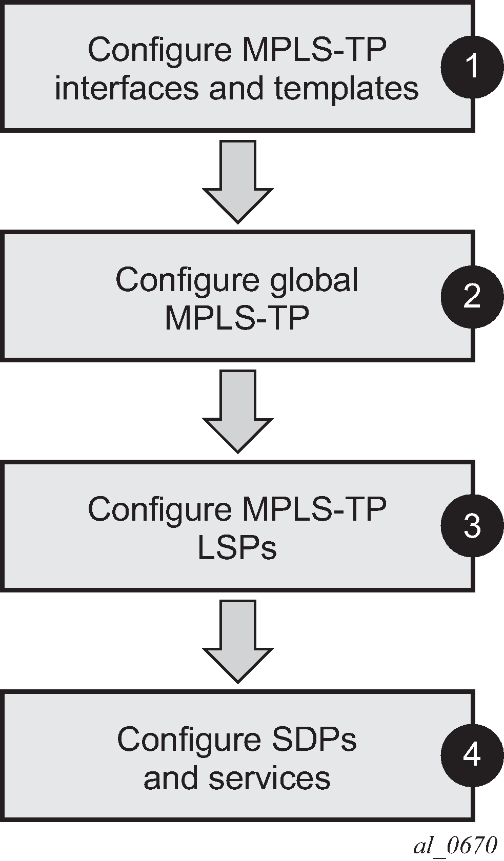
MPLS-TP configuration steps shows the configuration process to be followed when setting up MPLS-TP.
Configure MPLS-TP interfaces and templates
MPLS-TP LSPs can use either numbered or unnumbered network IP interfaces, or unnumbered network interfaces that have been configured to operate without relying on IP routing. This non-IP interface type does not have an IP address associated with it and may be configured to have either a unicast, broadcast or multicast MAC address. The intent of using a broadcast or multicast MAC address is to enable a standard set of MAC addresses to be configured for a network without requiring any changes to the configuration of neighboring router interfaces each time an interface to which a router is connected is changed. If a broadcast or multicast MAC address is used, then the operator should take care that only a point-to-point link is connected to the Ethernet port used by the interface. Otherwise, MPLS-TP packets may be replicated to each remote port to which the link is connected.
The non-IP network interface type is known as an unnumbered MPLS-TP interface. Only MPLS-TP can use this interface type; other IP protocols are blocked from using it. Also, address resolution protocol (ARP) is not used for next hop resolution. This example uses unnumbered MPLS-TP interfaces.
Unnumbered MPLS-TP interfaces are configured on each network-facing interface for the nodes in the MPLS-TP domain, as shown in the following output. This is done using the unnumbered-mpls-tp keyword at create time. In addition, the static-arp unnumbered command is used to set the next hop unicast, broadcast, or multicast MAC address of the interface. The system interface must also be configured. Numbered IP network interfaces, bound to port 1/1/c4/1 of PE-2 and port 1/1/c2/1 of PE-4 are used for the IP/MPLS portion of the network in MPLS-TP example network showing LSPs.
# on PE-1:
configure
    router Base
        interface "int-PE-1-P-3" unnumbered-mpls-tp
            port 1/1/c2/1
            static-arp unnumbered 01:00:5e:90:00:00
            no shutdown
        exit
        interface "int-PE-1-PE-2" unnumbered-mpls-tp
            port 1/1/c1/1
            static-arp unnumbered 01:00:5e:90:00:00
            no shutdown
        exit
        interface "system"
            address 192.0.2.1/32
            no shutdown
        exit
        autonomous-system 64511
# on PE-2:
configure
    router Base
        interface "int-PE-2-P-3" unnumbered-mpls-tp
            port 1/1/c1/1
            static-arp unnumbered 01:00:5e:90:00:00
            no shutdown
        exit
        interface "int-PE-2-PE-1" unnumbered-mpls-tp
            port 1/1/c2/1
            static-arp unnumbered 01:00:5e:90:00:00
            no shutdown
        exit
        interface "int-PE-2-PE-4"
            address 192.168.24.1/30
            port 1/1/c4/1
            no shutdown
        exit
        interface "system"
            address 192.0.2.2/32
            no shutdown
        exit
        autonomous-system 65535
        static-route-entry 192.0.2.4/32
            next-hop 192.168.24.2
                no shutdown
            exit
        exit
# on P-3:
configure
    router Base
        interface "int-P-3-PE-1" unnumbered-mpls-tp
            port 1/1/c1/1
            static-arp unnumbered 01:00:5e:90:00:00
            no shutdown
        exit
        interface "int-P-3-PE-2" unnumbered-mpls-tp
            port 1/1/c2/1
            static-arp unnumbered 01:00:5e:90:00:00
            no shutdown
        exit
        interface "system"
            address 192.0.2.3/32
            no shutdown
        exit
        autonomous-system 65535
# on PE-4:
configure
    router Base
        interface "int-PE-4-PE-2"
            address 192.168.24.2/30
            port 1/1/c2/1
            no shutdown
        exit
        interface "system"
            address 192.0.2.4/32
            no shutdown
        exit
        autonomous-system 65535
        static-route-entry 192.0.2.2/32
            next-hop 192.168.24.1
                no shutdown
            exit
        exit
Next, MPLS should be configured on each of the interfaces to be used by MPLS-TP. As an example, only the configuration on PE-1 is shown although a similar configuration is provisioned on PE-2 and P-3.
# on PE-1:
configure
    router Base
        mpls
            mpls-tp
            exit
            interface "system"
                no shutdown
            exit
            interface "int-PE-1-P-3"
                no shutdown
            exit
            interface "int-PE-1-PE-2"
                no shutdown
            exit
            no shutdown
        exit
PE-4 is an IP/MPLS only node so there is no MPLS TP configuration
# on PE-4:
configure
    router Base
        mpls
            interface "system"
                no shutdown
            exit
            interface "int-PE-4-PE-2"
                no shutdown
            exit
            no shutdown
        exit
The mpls context must be in the no shutdown state to enable MPLS-TP.
Static labels are used by MPLS-TP LSPs and PWs. By default, SR OS splits the full range in a static and a dynamic range, and these ranges are as follows:
*A:PE-1# show router mpls-labels label-range

============================================================================
Label Ranges
============================================================================
Label Type      Start Label End Label   Aging       Available   Total
----------------------------------------------------------------------------
Static          32          18431       -           18400       18400
Dynamic         18432       524287      0           505856      505856
    Seg-Route   0           0           -           0           0
============================================================================
This can be modified by configuration. To reserve 2000 labels starting from label 32, the following command is launched:
# on PE-1:
configure
    router Base
        mpls-labels
            static-label-range 2000
As a result, the range from label 32 to 2031 is reserved for static labels.
*A:PE-1# show router mpls-labels label-range

============================================================================
Label Ranges
============================================================================
Label Type      Start Label End Label   Aging       Available   Total
----------------------------------------------------------------------------
Static          32          2031        -           2000        2000
Dynamic         2032        524287      0           522256      522256
    Seg-Route   0           0           -           0           0
============================================================================
In this case, there is no need to modify the range for static labels. The labels that will be chosen are in the default range.
Next, one or more BFD templates are configured on the LERs. These templates are used to define BFD state machine parameters used for BFD continuity check (CC) on an LSP, including the transmit and receive timer intervals (in milliseconds). CPM network processor BFD is required if timer intervals as short as 10 ms are to be used, but depending on the platform, 100 ms BFD may use CPU-based BFD.
*A:PE-1>config>router# bfd ?
  - bfd

      abort           - Discard the changes that have been made to bfd template
                        during a session
      begin           - Switch to edit mode for bfd template - use commit to save or
                        abort to discard the changes made in a session
 [no] bfd-template    + Configure a bfd template
      commit          - Save the changes made to bfd template during a session
      seamless-bfd    + Configure Seamless BFD
*A:PE-1>config>router>bfd# bfd-template ?
  - bfd-template <[32 chars max]>
  - no bfd-template <[32 chars max]>


 [no] echo-receive    - Configure echo receive interval
 [no] multiplier      - Configure multiplier
 [no] receive-interv* - Configure receive interval
 [no] transmit-inter* - Configure transmit interval
 [no] type            - Configure the bfd session endpoint type
A subset of these parameters is used by MPLS-TP BFD sessions, as follows:
transmit-interval <milli-seconds [10..100000]> and the receive-interval <milli-seconds [10..100000]> — These are the transmit and receive timers for BFD packets. For MPLS-TP, these are the timers used by BFD CC packets. Values are in milliseconds: 10 ms to 100,000 ms, with 1 ms granularity. Default 10 ms for CPM3 or higher. The minimum interval that can be supported is hardware dependent. For MPLS-TP BFD connectivity verification (CV) packets, a transmit interval of 1000 ms is used.
multiplier <integer [1..20]>. Default: 3. —The configured multiplier parameter is used for MPLS-TP CC BFD sessions. The multiplier parameter is ignored for MPLS-TP combined CC/CV BFD sessions, and the default of 3 is used.
type cpm-np — Type CPM-NP selects the CPM network processor as the local termination point for the BFD session, which is used by default for MPLS-TP. Type CPM-NP is needed to configure a transmit interval down to 10 ms.
The following CLI illustrates the BFD template configuration at PE-1. Default parameters are sufficient, so only the BFD template name is configured. BFD templates use a begin-commit model for configuration. Create or modify a template with the begin statement. Changes to an existing template or the creation of a new template is not effected until the commit statement is entered.
# on PE-1:
configure
    router Base
        bfd
            begin
            bfd-template "default-bfd"
            exit
            commit
The following info detail command shows the values that are assigned by default.
*A:PE-1>config>router>bfd# info detail
----------------------------------------------
            bfd-template "default-bfd"
                no type
                transmit-interval 100
                receive-interval 100
                multiplier 3
                echo-receive 100
            exit
            seamless-bfd
            exit
----------------------------------------------
To avoid confusion when the configured intervals differ from the negotiated intervals on sims, a BFD template with intervals of 1000 ms is configured and used in this chapter.
# on PE-1, PE-2:
configure
    router Base
        bfd
            begin
            bfd-template "tp-bfd"
                transmit-interval 1000
                receive-interval 1000
            exit
            commit
Configure global MPLS-TP parameters
MPLS-TP global parameters are configured in the configure router mpls mpls-tp context. The MPLS-TP global parameters include the MPLS-TP identifiers for the node and the range of tunnel identifiers that should be reserved for MPLS-TP LSPs.
Node identifiers include the global ID and the node ID. The node ID may be defined as an unsigned integer or use dotted quad notation (a.b.c.d), but the node ID does not have to be a routable IP address.
The CLI tree for configuring the MPLS-TP identifiers for a node is as follows:
*A:PE-1>config>router>mpls# mpls-tp ?
  - mpls-tp
  - no mpls-tp

 [no] global-id       - Global id for MPLS-TP
 [no] node-id         - Node id for MPLS-TP local router
 [no] oam-template    + Configure a MPLS-TP OAM Template
 [no] protection-tem* + Configure a MPLS-TP Protection Template
 [no] shutdown        - Administratively enable/disable the MPLS-TP
 [no] tp-tunnel-id-r* - Configure MPLS-TP tunnel id range on the ingress router
 [no] transit-path    + Configure a MPLS-TP Transit Path
The default value for the global ID is 0. This is used if the global ID is not configured. If an operator expects that inter-domain LSPs will be configured, then it is recommended to set the global ID to the local autonomous system number (ASN) of the node, as configured in the configure router context, to ensure that the combination of global ID and node ID is globally unique. If two-byte ASNs are used, then the two most significant bytes of the global ID are padded with zeros.
The default value of the node ID is the system interface IPv4 address. The configure router mpls mpls-tp context cannot be administratively enabled unless at least a system interface IPv4 address is configured, because MPLS requires that this value be configured.
In order to change the values, configure router mpls mpls-tp must be administratively disabled (shutdown). This will bring down all the MPLS-TP LSPs on the node. New values are propagated to the system when a no shutdown is performed.
The following CLI shows the MPLS-TP node identifier configuration for PE-1.
# on PE-1:
configure
    router Base
        mpls
            mpls-tp
                global-id 64511
                node-id 10.0.0.1
            exit
A similar configuration is implemented in all routers in this chapter, except that the node IDs must be different (PE-2 has node ID 10.0.0.2 and P-3 node ID 10.0.0. 3). In this example, the global ID for PE-2 and P-3 equals 65535.
# on PE-2:
configure
    router Base
        mpls
            mpls-tp
                global-id 65535
                node-id 10.0.0.2
            exit
Next, protection and OAM templates must be configured at the MPLS-TP LERs. A protection template defines the parameters for the linear protection state coordination mechanism. MPLS-TP linear protection is specified in RFC 6378. It provides protection for an LSP using a working and a protect path. A protection state coordination (PSC) protocol is used by the LERs at each end of the protected LSP to coordinate whether the working or protect path is used for forwarding. BFD is run on both the working and protect paths.
The linear protection parameters include revertive or non-revertive behavior, the wait-to-restore timer, the rapid-psc-timer and the slow-psc-timer. The wait-to-restore timer (in seconds) defines the time to wait before reverting to the working path if, on restoration of connectivity, the revertive behavior is selected.
The following command is used to configure the protection template:
*A:PE-1>config>router>mpls>tp# protection-template ?
  - no protection-template <[32 chars max]>
  - protection-template <[32 chars max]>


      rapid-psc-timer - Configure the rapid Protection Switch Coordination (PSC) timer
 [no] revertive       - Enable/Disable the template's revertive mode
      slow-psc-timer  - Configure the slow Protection Switch Coordination (PSC) timer
 [no] wait-to-restore - Configure the WTR timer for the template
See the CLI command descriptions in the 7450 ESS, 7750 SR, 7950 XRS, and VSR MPLS Guide and the 7450 ESS, 7750 SR, 7950 XRS, and VSR Classic CLI Command Reference Guide for further details of these commands.
The OAM template defines generic proactive OAM parameters, such as BFD hold down and hold up timer values (which can be used to introduce some hysteresis if BFD bounces) and the BFD template to use.
The following command is used to configure the OAM template:
*A:PE-1>config>router>mpls>tp# oam-template ?
  - no oam-template <template-name>
  - oam-template <template-name>

 <template-name>      : [32 chars max]


 [no] bfd-template    - Configure the Bidirectional Forwarding Detection (BFD) template
 [no] hold-time-down  - Configure hold-down dampening timer
 [no] hold-time-up    - Configure the hold-up dampening timer
See the CLI command descriptions in the 7450 ESS, 7750 SR, 7950 XRS, and VSR MPLS Guide and the 7450 ESS, 7750 SR, 7950 XRS, and VSR Classic CLI Command Reference Guide for further details of these commands.
MPLS-TP requires the reservation of a tunnel ID range, dedicated for the use of MPLS-TP LSPs. This range is reserved using the following CLI tree:
*A:PE-1>config>router>mpls>tp# tp-tunnel-id-range ?
  - tp-tunnel-id-range <min> <max>
  - no tp-tunnel-id-range

 <min>                : [1..61440]
 <max>                : [1..61440]
PE-1 and PE-2 have the same protection and OAM templates configured, as follows:
# on PE-1, PE-2:
configure
    router Base
        mpls
            mpls-tp
                tp-tunnel-id-range 100 1000
                protection-template "tp-protect"
                exit
                oam-template "tp-oam"
                    bfd-template "tp-bfd"
                exit
                no shutdown
            exit
Configure MPLS-TP LSPs
When the global MPLS-TP parameters have been configured, the system is ready to configure MPLS-TP LSPs. An MPLS-TP LSP is configured under the configure router mpls lsp context.
Because LSP labels are statically configured, both ends of the LSP must be explicitly configured. The LSP paths must also be explicitly configured in the LSR nodes. MPLS-TP LSPs must use the mpls-tp keyword including a source tunnel number at create time.
The following commands are used to configure an MPLS-TP LSP at an LER:
configure
    router Base
        mpls
            lsp <lsp-name> mpls-tp <src-tunnel-num>
                to node-id {a.b.c.d|<1..4294967295>}
                dest-global-id [0..4294967295]
                dest-tunnel-number [1..61440]
                [no] working-tp-path
                    [no] lsp-num [1..65535]
                    in-label [32..18431]
                    out-label [16..1048575] out-link <interface-name> [next-hop <ip-address>]
                    [no] mep
                        [no] oam-template <[32 chars max]>
                        [no] bfd-enable [cc|cc-cv}
                        [no] bfd-trap-suppression
                        [no] dsmap <in-if-num>[:<out-if-num>]
                        [no] shutdown
                    exit
                    [no] shutdown
                exit
                [no] protect-tp-path
                     [no] lsp-num [1..65535]
                     in-label [32..18431]
                     out-label [16..1048575] out-link <interface-name> [next-hop <ip-address>]
                     [no] mep
                         [no] protection-template <[256 chars max]>
                         [no] oam-template <[32 chars max]>
                         [no] bfd-enable [cc|cc-cv}
                         [no] bfd-trap-suppression
                         [no] dsmap <in-if-num>[:<out-if-num>]
                         [no] shutdown
                     exit
                     [no] shutdown
                 exit
                 [no] shutdown
See the CLI command descriptions in the 7450 ESS, 7750 SR, 7950 XRS, and VSR MPLS Guide and the 7450 ESS, 7750 SR, 7950 XRS, and VSR Classic CLI Command Reference Guide for further details of these commands.
A working path and a protect path for LSP "LSP-PE-1-P-2" must be configured between PE-1 and PE-2. Each LSP is configured with the full set of MPLS-TP identifiers required to build the LSP ID. Each working path and protect path must have an incoming label, outgoing label, and outgoing link configured.
Each working path and protect path also includes a maintenance entity group end-point (MEP) configuration, under which the applicable OAM template is configured. BFD is also enabled under the mep context for the path. In this example, BFD operating in CC mode is enabled on the working and protect paths. The protection template, containing parameters for linear protection, is only applied under the protect path context.
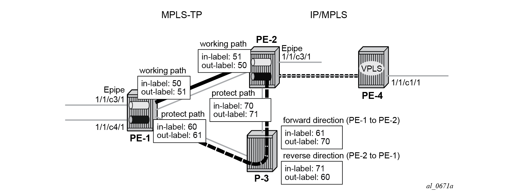
LSP path label value configurations shows the LSP working and protect path label values configured at PE-1, PE-2, and P-3. At each node, the outgoing label must match the incoming label on the next hop for a specific direction. At the LERs (PE-1 and PE-2), the incoming and outgoing label values for each LSP path are configured together. At the LSR (P-3), the label values for the label mapping between ingress and egress for each direction of the path (that is, forward and reverse) are configured together.
The following shows the LER LSP configuration of PE-1 and PE-2.
# on PE-1:
configure
    router Base
        mpls
            lsp "LSP-PE-1-PE-2" mpls-tp 100
                to node-id 10.0.0.2
                dest-global-id 65535
                dest-tunnel-number 100
                working-tp-path
                    in-label 50
                    out-label 51 out-link "int-PE-1-PE-2"
                    mep
                        oam-template "tp-oam"
                        bfd-enable cc
                        no shutdown
                    exit
                    no shutdown
                exit
                protect-tp-path
                    in-label 60
                    out-label 61 out-link "int-PE-1-P-3"
                    mep
                        protection-template "tp-protect"
                        oam-template "tp-oam"
                        bfd-enable cc
                        no shutdown
                    exit
                    no shutdown
                exit
                no shutdown
            exit
            no shutdown
        exit
# on PE-2:
configure
    router Base
        mpls
           lsp "LSP-PE-1-PE-2" mpls-tp 100
                to node-id 10.0.0.1
                dest-global-id 64511
                dest-tunnel-number 100
                working-tp-path
                    in-label 51
                    out-label 50 out-link "int-PE-2-PE-1"
                    mep
                        oam-template "tp-oam"
                        bfd-enable cc
                        no shutdown
                    exit
                    no shutdown
                exit
                protect-tp-path
                    in-label 70
                    out-label 71 out-link "int-PE-2-P-3"
                    mep
                        protection-template "tp-protect"
                        oam-template "tp-oam"
                        bfd-enable cc
                        no shutdown
                    exit
                    no shutdown
                exit
                no shutdown
            exit
            no shutdown
        exit
This example requires a protect path to be switched via P-3, therefore, a transit path must be configured in P-3. The CLI tree for configuring MPLS-TP transit paths is as follows:
configure
    router Base
        mpls
            mpls-tp
                transit-path <path-name [32 chars max]>
                    [no] path-id [src-global-id <global-id [0..4294967295]>]
                                 src-node-id <node-id [a.b.c.d|<1..4294967295>]>
                                 src-tunnel-num <tunnel-num [1..61440]>
                                 [dest-global-id <global-id [0..4294967295]>]
                                 dest-node-id <node-id [a.b.c.d|<1..4294967295>]>
                                 [dest-tunnel-num <tunnel-num [1..61440]>]
                                 lsp-num <lsp-num [1..65535]>
                    [no] forward-path
                        in-label <in-label [32..18431]>
                                 out-label <out-label [16..1048575]>
                                 out-link <interface-name [32 chars max]>
                                 [next-hop <ip-address [a.b.c.d]>]
                        [no] mip
                            [no] dsmap <in-if-num>[:<out-if-num>]
                        exit
                    exit
                    [no] reverse-path
                        in-label <in-label [32..18431]>
                                 out-label <out-label [16..1048575]>
                                 out-link <interface-name [32 chars max]>
                                 [next-hop <ip-address [a.b.c.d]>]
                        [no] mip
                            [no] dsmap <in-if-num>[:<out-if-num>]
                        exit
                    exit
                    [no] shutdown
See the CLI command descriptions in the 7450 ESS, 7750 SR, 7950 XRS, and VSR MPLS Guide and the 7450 ESS, 7750 SR, 7950 XRS, and VSR Classic CLI Command Reference Guide for further details of these commands.
The CLI configuration for the forward and reverse directions of the transit path (that is, the protect path of the LSP) at P-3 is as follows:
# on P-3:
configure
    router Base
        mpls
            mpls-tp
                global-id 65535
                node-id 10.0.0.3
                transit-path "LSP-PE-1-PE-2"
                    forward-path
                        in-label 61 out-label 70 out-link "int-P-3-PE-2"
                    exit
                    reverse-path
                        in-label 71 out-label 60 out-link "int-P-3-PE-1"
                    exit
                    path-id src-global-id 64511 src-node-id 10.0.0.1 src-tunnel-num 100
                            dest-global-id 65535 dest-node-id 10.0.0.2
                            dest-tunnel-num 100 lsp-num 2
                    no shutdown
                exit
                no shutdown
            exit
            no shutdown
        exit
The example also requires an LSP across the IP/MPLS network to backhaul traffic from PE-2 at the edge of the MPLS-TP network to the VPLS service hosted in PE-4. An RSVP LSP is configured at PE-2 for this purpose, as follows:
# on PE-2:
configure
    router Base
        mpls
            interface "int-PE-2-PE-4"
                no shutdown
            exit
            path "empty"
                no shutdown
            exit
            lsp "LSP-PE-2-PE-4"
                to 192.0.2.4
                primary "empty"
                exit
                no shutdown
            exit
            no shutdown
        exit
        rsvp
            no shutdown
        exit
Create a T-LDP session toward PE-4. LDP over RSVP is preferred (prefer-tunnel-in-tunnel).
# on PE-2:
configure
    router Base
        ldp
            prefer-tunnel-in-tunnel
            targeted-session
                peer 192.0.2.4
                exit
            exit
        exit
A similar configuration is implemented in PE-4.
At this point in the configuration process, it is recommended to verify the MPLS-TP LSP configuration and operation of BFD and linear protection.
First, check that the BFD sessions on both the working and protect paths are up:
*A:PE-1# show router bfd session

===============================================================================
Legend:
  Session Id = Interface Name | LSP Name | Prefix | RSVP Sess Name | Service Id
  wp = Working path   pp = Protecting path
===============================================================================
BFD Session
===============================================================================
Session Id                                        State      Tx Pkts    Rx Pkts
  Rem Addr/Info/SdpId:VcId                      Multipl     Tx Intvl   Rx Intvl
  Protocols                                        Type     LAG Port     LAG ID
  Loc Addr                                                             LAG name
-------------------------------------------------------------------------------
wp::LSP-PE-1-PE-2                                    Up          N/A        N/A
  65535::10.0.0.2                                     3         1000       1000
  mplsTp                                         cpm-np          N/A        N/A
  0.0.0.0
pp::LSP-PE-1-PE-2                                    Up          N/A        N/A
  65535::10.0.0.2                                     3         1000       1000
  mplsTp                                         cpm-np          N/A        N/A
  0.0.0.0
-------------------------------------------------------------------------------
No. of BFD sessions: 2
===============================================================================
Next, check the currently active path. This can be done using the oam lsp-trace command. The static option must be specified for MPLS-TP LSPs.
*A:PE-1# oam lsp-trace static "LSP-PE-1-PE-2"
lsp-trace to LSP-PE-1-PE-2: 0 hops min, 0 hops max, 100 byte packets
1  GlobalId 65535 NodeId 10.0.0.2
   rtt=0.564ms rc=3(EgressRtr)
The static LSP trace shows that data packets currently follow the working path of the LSP (no transit node is shown).
In order to test the operation of linear protection, the port used by the working path can be disabled, and the BFD session state checked again:
# on PE-1:
configure
    port 1/1/c1/1
        shutdown
*A:PE-1# show router bfd session

===============================================================================
Legend:
  Session Id = Interface Name | LSP Name | Prefix | RSVP Sess Name | Service Id
  wp = Working path   pp = Protecting path
===============================================================================
BFD Session
===============================================================================
Session Id                                        State      Tx Pkts    Rx Pkts
  Rem Addr/Info/SdpId:VcId                      Multipl     Tx Intvl   Rx Intvl
  Protocols                                        Type     LAG Port     LAG ID
  Loc Addr                                                             LAG name
-------------------------------------------------------------------------------
wp::LSP-PE-1-PE-2                                  Down          N/A        N/A
  65535::10.0.0.2                                     3         1000       1000
  mplsTp                                         cpm-np          N/A        N/A
  0.0.0.0
pp::LSP-PE-1-PE-2                                    Up          N/A        N/A
  65535::10.0.0.2                                     3         1000       1000
  mplsTp                                         cpm-np          N/A        N/A
  0.0.0.0
-------------------------------------------------------------------------------
No. of BFD sessions: 2
===============================================================================
Execute LSP trace again to check that the LSP has failed over to use the protect path:
*A:PE-1# oam lsp-trace static  "LSP-PE-1-PE-2"
lsp-trace to LSP-PE-1-PE-2: 0 hops min, 0 hops max, 100 byte packets
1  GlobalId 65535 NodeId 10.0.0.3
   rtt=0.585ms rc=8(DSRtrMatchLabel)
2  GlobalId 65535 NodeId 10.0.0.2
   rtt=1.07ms rc=3(EgressRtr)
This shows that packets are now forwarded via the protect path through P-3, which has node ID 10.0.0.3.
Finally bring the LSP back to the working path by bringing port 1/1/c1/1 up, and either waiting for the LSP to revert to the working path or forcing it onto the working path and clearing the revert timer by executing a tools command as follows:
# on PE-1:
configure
    port 1/1/c1/1
        no shutdown
*A:PE-1# tools perform router mpls tp-tunnel force "LSP-PE-1-PE-2"
*A:PE-1# tools perform router mpls tp-tunnel clear "LSP-PE-1-PE-2"
*A:PE-1# oam lsp-trace static "LSP-PE-1-PE-2"
lsp-trace to LSP-PE-1-PE-2: 0 hops min, 0 hops max, 100 byte packets
1  GlobalId 65535 NodeId 10.0.0.2
   rtt=0.582ms rc=3(EgressRtr)
Configure SDPs and services
Services can be configured to use MPLS-TP LSPs when the LSP configuration is completed. SDPs and services are configured in a similar manner to those using static-labeled pseudowires without MPLS-TP.
Distributed services are configured to use MPLS-TP with the following steps:
Configure an SDP with signaling off. With signaling off, the SDP far-end may then be configured as an MPLS-TP node ID or an IPv4 address. SDP keep-alive is disabled.
Configure the service, including the spoke-SDP using the SDP. To use MPLS-TP, the spoke-SDP must have statically assigned ingress and egress labels, the control word must be enabled, and it must have an MPLS-TP identifier for the PW (the PW path ID) configured. This is comprised of two parts, a source attachment individual identifier (SAII) and a target attachment individual identifier (TAII), both of which must be configured. Control channel status signaling may also be configured to support PW status signaling on the static MPLS-TP PW.
In this example, an SDP is configured to use the MPLS-TP LSP from PE-1 to PE-2, which will act as a transport for the static MPLS-TP PWs corresponding to Epipe 10 and Epipe 20. Another SDP is configured for the targeted LDP (T-LDP) PW segment corresponding to Epipe 20 between PE-2 and PE-4.
The following CLI shows the SDP between PE-1 and PE-2 and the SDP between PE-2 and PE-4:
# on PE-1:
configure
    service
        sdp 1 mpls create
            signaling off
            far-end node-id 10.0.0.2 global-id 65535
            lsp "LSP-PE-1-PE-2"
            no shutdown
        exit
# on PE-2:
configure
    service
        sdp 1 mpls create
            signaling off
            far-end node-id 10.0.0.1 global-id 64511
            lsp "LSP-PE-1-PE-2"
            no shutdown
        exit
        sdp 2 mpls create
            far-end 192.0.2.4
            lsp "LSP-PE-2-PE-4"
            no shutdown
        exit
# on PE-4:
configure
    service
        sdp 2 mpls create
            far-end 192.0.2.2
            lsp "LSP-PE-4-PE-2"
            no shutdown
        exit
Next, configure the services that will use the MPLS-TP LSPs.
The service configuration CLI tree for an Epipe service using MPLS-TP is as follows:
configure
    service
        epipe <service-id> [name <name>] customer <customer-id> create
            [no] spoke-sdp <sdp-id:vc-id>
                [no] hash-label
                [no] standby-signaling-slave
            [no] spoke-sdp <sdp-id:vc-id> [vc-type {ether|vlan}] [create] [no-endpoint]
                egress
                    [no] vc-label <out-label>
                ingress
                    [no] vc-label <in-label>
    -           [no] control-word
                [no] pw-path-id
                     [no] agi <agi>
                     [no] saii-type2 <global-id:node-id:ac-id>
                     [no] taii-type2 <global-id:node-id:ac-id>
                 exit
                 control-channel-status
                     [no] acknowledgment
                     [no] refresh-timer <seconds [10..65535]>
                     [no] request-timer <secs> retry-timer <secs> [timeout-multiplier <value>]
                     [no] shutdown
See the CLI command descriptions in the 7450 ESS, 7750 SR, 7950 XRS, and VSR MPLS Guide and the 7450 ESS, 7750 SR, 7950 XRS, and VSR Classic CLI Command Reference Guide for further details of these commands.
The following CLI examples show the Epipe service configuration at PE-1, PE-2, and the VPLS spoke-SDP termination point at PE-4.
Epipe 10 belongs to customer 1, and Epipe 20 belongs to customer 2 in this example.
# on PE-1:
configure
    service
        epipe 10 name "Epipe 10" customer 1 create
            sap 1/1/c3/1 create
                no shutdown
            exit
            spoke-sdp 1:10 create
                ingress
                    vc-label 150
                exit
                egress
                    vc-label 151
                exit
                control-word
                pw-path-id
                    saii-type2 64511:10.0.0.1:1
                    taii-type2 65535:10.0.0.2:1
                exit
                control-channel-status
                    no shutdown
                exit
                no shutdown
            exit
            no shutdown
        exit
        epipe 20 name "Epipe 20" customer 2 create
            sap 1/1/c4/1 create
                no shutdown
            exit
            spoke-sdp 1:20 create
                ingress
                    vc-label 200
                exit
                egress
                    vc-label 201
                exit
                control-word
                pw-path-id
                    saii-type2 64511:10.0.0.1:2
                    taii-type2 65535:10.0.0.2:2
                exit
                control-channel-status
                    no shutdown
                exit
                no shutdown
            exit
            no shutdown
        exit
At PE-2, Epipe 10 terminates on a SAP on port 1/1/c3/1, while Epipe 20 is switched between a static MPLS-TP PW segment (spoke-SDP 1:20) and a T-LDP signaled PW segment (spoke-SDP 2:1) for backhaul to the remote PE-4 containing the VPLS service.
# on PE-2:
configure
    service
        epipe 10 name "Epipe 10" customer 1 create
            sap 1/1/c3/1 create
                no shutdown
            exit
            spoke-sdp 1:10 create
                ingress
                    vc-label 151
                exit
                egress
                    vc-label 150
                exit
                control-word
                pw-path-id
                    saii-type2 65535:10.0.0.2:1
                    taii-type2 64511:10.0.0.1:1
                exit
                control-channel-status
                    no shutdown
                exit
                no shutdown
            exit
            no shutdown
        exit
        epipe 20 name "Epipe 20" customer 2 vc-switching create
            spoke-sdp 1:20 create
                ingress
                    vc-label 201
                exit
                egress
                    vc-label 200
                exit
                control-word
                pw-path-id
                    saii-type2 65535:10.0.0.2:2
                    taii-type2 64511:10.0.0.1:2
                exit
                control-channel-status
                    no shutdown
                exit
                no shutdown
            exit
            spoke-sdp 2:1 create
                control-word
                no shutdown
            exit
            no shutdown
        exit
At PE-4, the T-LDP signaled PW segment for Epipe 20 is terminated on a VPLS service:
# on PE-4:
configure
    service
        customer 2 name "VPLS-MPLS-TP customer" create
            description "VPLS-MPLS-TP customer"
        exit
        vpls 1 name "VPLS 1" customer 2 create
            sap 1/1/c1/1 create
                no shutdown
            exit
            spoke-sdp 2:1 create
                control-word
                no shutdown
            exit
            no shutdown
        exit
Epipe 10 uses a static MPLS-TP PW from end to end, which can be tested using the virtual circuit connectivity verification vccv-ping command at PE-1, as follows:
*A:PE-1# oam vccv-ping static 1:10
VCCV-PING 1:10 84 bytes MPLS payload
Seq=1, send from intf int-PE-1-PE-2
       send from lsp LSP-PE-1-PE-2
       reply via Control Channel
       src id tlv received: GlobalId 65535 NodeId 10.0.0.2
       cv-data-len=44 rtt=0.597ms rc=3 (EgressRtr)

---- VCCV PING 1:10 Statistics ----
1 packets sent, 1 packets received, 0.00% packet loss
round-trip min = 0.597ms, avg = 0.597ms, max = 0.597ms, stddev = 0.000ms
The operation of control channel status signaling can also be verified for this Epipe, as follows:
Disable the port the SAP on PE-2 is using:
# on PE-2:
configure
    port 1/1/c3/1
       shutdown
The PW peer status bits for the spoke-SDP for Epipe 10, signaled using control channel status signaling, can be displayed at node PE-1 using the following command (some of the show command output has been removed for brevity). The peer PW status bits are shown in bold in the following output.
*A:PE-1# show service id 10 sdp detail

===============================================================================
Services: Service Destination Points Details
===============================================================================
-------------------------------------------------------------------------------
 Sdp Id 1:10  -(10.0.0.2:65535)
-------------------------------------------------------------------------------
Description     : (Not Specified)
SDP Id             : 1:10                     Type              : Spoke
Spoke Descr     : (Not Specified)
VC Type            : Ether                    VC Tag            : n/a
Admin Path MTU     : 0                        Oper Path MTU     : 8914
Delivery           : MPLS
Far End            : 10.0.0.2:65535           Tunnel Far End    : n/a
Oper Tunnel Far End: n/a
LSP Types          : MPLSTP
---snip---

Ingress Label      : 150                      Egress Label      : 151
---snip---

Flags              : None
Local Pw Bits      : None
Peer Pw Bits       : lacIngressFault lacEgressFault
Peer Fault Ip      : None
Peer Vccv CV Bits  : None
Peer Vccv CC Bits  : None
---snip---
Epipe 20 uses a static MPLS-TP PW from PE-1 to PE-2, identified by a static PW forwarding equivalence class (FEC), and a T-LDP segment with FEC128 from PE-2 to PE-4. Therefore, the target FEC used for a VCCV-ping command from PE-1 to PE-4 is different from the local FEC for the PW at PE-1. VCCV-trace provides a useful tool to test the resulting multi-segment PW (MS-PW), as follows. The same associated channel type must be used for both segments. This is the IPv4 channel.
*A:PE-1# oam vccv-trace static 1:20 assoc-channel ipv4 detail
VCCV-TRACE 1:20  with 116 bytes of MPLS payload
1  192.0.2.2 GlobalId 65535 NodeId 10.0.0.2
   rtt=0.599ms rc=8(DSRtrMatchLabel)
   Next segment: VcId=1 VcType=Ether Source=192.0.2.2 Remote=192.0.2.4
2  192.0.2.4  rtt=1.06ms rc=3(EgressRtr)
The system supports the interworking of control channel status on a static MPLS-TP PW segment with T-LDP-signaled PW status on a T-LDP PW segment. This can be verified as follows.
Disable the port the spoke SDP on PE-4 is using:
# on PE-4:
configure
    port 1/1/c2/1
        shutdown
The PW peer status bits for the spoke-SDP for Epipe 20 can then be displayed at node PE-1 using the following command (some of the show command output has been removed for brevity). The peer PW status bits are shown in bold in the following output.
*A:PE-1# show service id 20 sdp detail

===============================================================================
Services: Service Destination Points Details
===============================================================================
-------------------------------------------------------------------------------
 Sdp Id 1:20  -(10.0.0.2:65535)
-------------------------------------------------------------------------------
Description     : (Not Specified)
SDP Id             : 1:20                     Type              : Spoke
Spoke Descr     : (Not Specified)
VC Type            : Ether                    VC Tag            : n/a
Admin Path MTU     : 0                        Oper Path MTU     : 8914
Delivery           : MPLS
Far End            : 10.0.0.2:65535           Tunnel Far End    : n/a
Oper Tunnel Far End: n/a
LSP Types          : MPLSTP

---snip---

Ingress Label      : 200                      Egress Label      : 201
---snip---

Flags              : None
Local Pw Bits      : None
Peer Pw Bits       : psnIngressFault psnEgressFault
Peer Fault Ip      : None
Peer Vccv CV Bits  : None
Peer Vccv CC Bits  : None
---snip---
Conclusion
SR OS supports extensive MPLS transport profile (MPLS-TP) capabilities. MPLS-TP is intended to allow MPLS to be operated in a manner similar to existing transport technologies, with proactive in-band and on-demand operations and maintenance (OAM), and protection mechanisms that do not rely on a control plane to operate. SR OS nodes can operate both as an LER and LSR for MPLS-TP LSPs, and as a T-PE and S-PE for PWs with MPLS-TP OAM. An SR OS node can therefore act as a node within an MPLS-TP network, or as a gateway between MPLS-TP and IP/MPLS domains.
This example has illustrated a simple configuration, demonstrating the role of the SR OS router as an LER and LSR for MPLS-TP LSPs, and how its already extensive multi-service capabilities can be extended over an MPLS-TP network and between MPLS-TP and IP/MPLS networks.