Shared Risk Link Groups for Uncolored SR-MPLS Policy-based LSPs
This chapter provides information about Shared Risk Link Groups for uncolored SR-MPLS policy-based LSPs.
Topics in this chapter include:
Applicability
The configuration in the current edition corresponds to SRL Release 25.10.R2. There are no prerequisites.
Overview
Introduction
Shared Risk Link Group (SRLG) is a feature which allows the user to establish a standby or secondary label switched path (LSP) which is disjoint from the primary LSP. Links which are members of the same SRLG represent resources which share the same risk. For example, fiber links sharing the same conduit or multiple wavelengths sharing the same fiber.
A typical application of the SRLG feature is to provide an automatic placement of standby LSPs that minimize the probability of fate sharing with the primary LSP.
SRLGs are used to indicate which links share the same fate. The mechanism is similar to Multi-Protocol Label Switching (MPLS) admin groups. To advertise SRLGs, the information is part of the IGP TE parameters in an opaque link state advertisement (LSA). In IS-IS (RFC 4205), the SRLG is advertised in a Shared Risk Link Group TLV (type 138).
SRLG
Example topology shows the example topology for this chapter.
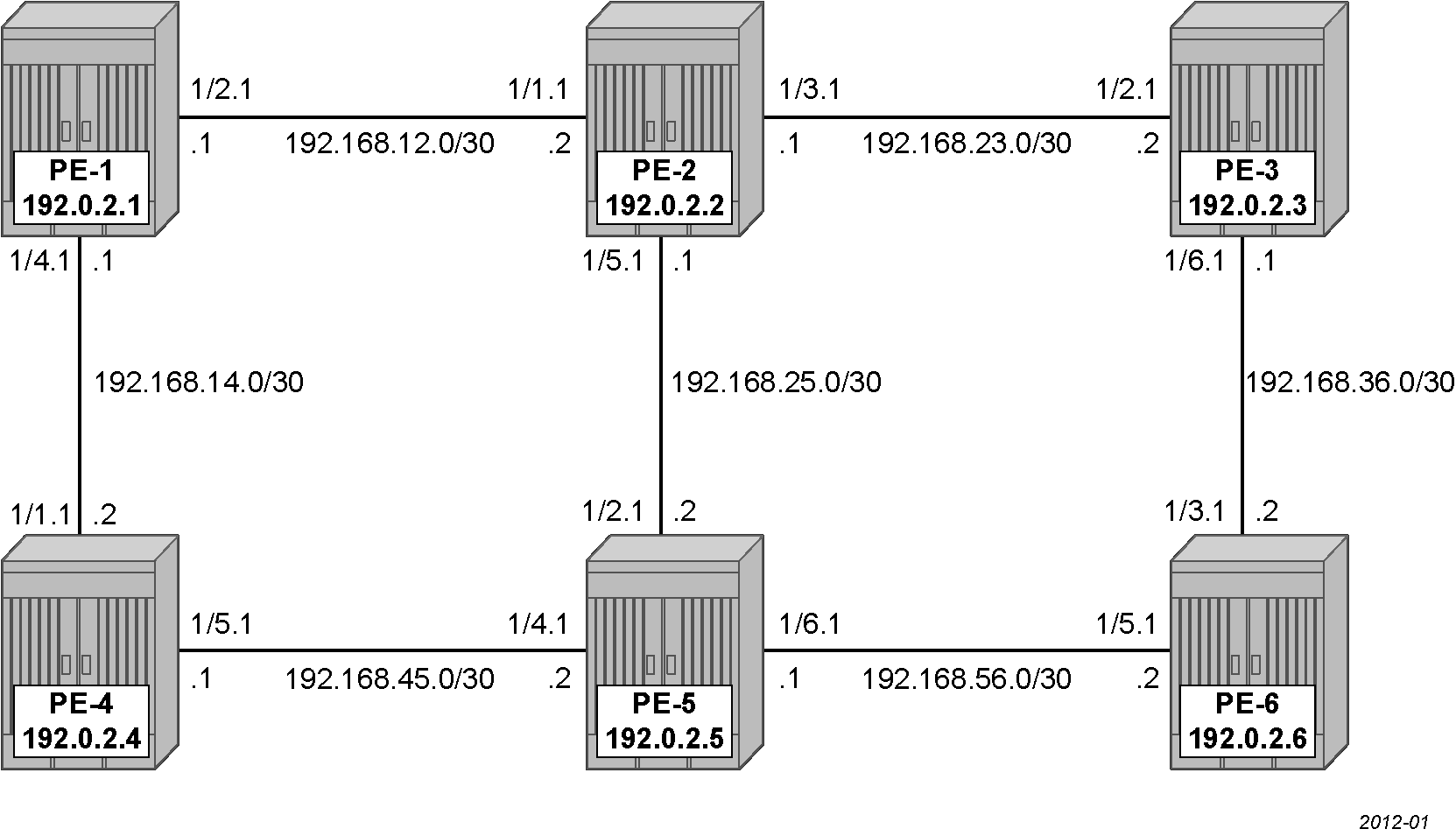
A single IGP area (IS-IS instance 0 in this case) with traffic engineering (TE) enabled is required for the SRLG feature to work properly.
Configuration
Configure the IP/MPLS network
IS-IS is configured on all interfaces. On PE-1, the initial configuration is the following:
# on PE-1:
    network-instance default {
        admin-state enable
        router-id 192.0.2.1
        interface ethernet-1/2.1 {
        }
        interface ethernet-1/4.1 {
        }
        interface system0.0 {
        }
        protocols {
            isis {
                instance 0 {
                    admin-state enable
                    level-capability L1
                    net [
                        49.0000.1920.0000.2001.00
                    ]
                    interface ethernet-1/2.1 {
                        admin-state enable
                        circuit-type point-to-point
                    }
                    interface ethernet-1/4.1 {
                        admin-state enable
                        circuit-type point-to-point
                    }
                    interface system0.0 {
                    }
                    level 1 {
                    }
                }
            }
        }
Segment routing is required on all nodes. The label ranges for the node SIDs and the adjacency SIDs are the following:
# on all nodes:
    system {
        mpls {
            label-ranges {
                static srgb-static-mpls {     # for protocol-independent node SIDs
                    shared true
                    start-label 100
                    end-label 799
                }
                dynamic srlb-dynamic-mpls {   # for dynamic adjacency SIDs
                    start-label 2100
                    end-label 2799
                }
Segment routing is configured on all nodes, as described in the Segment Routing with IS-IS Control Plane chapter. On PE-1, the segment routing configuration is as follows:
# on PE-1:
    network-instance default {
         protocols {
            isis {
                dynamic-label-block srlb-dynamic-mpls
                instance 0 {
                    segment-routing {
                        mpls {
                            dynamic-adjacency-sids {
                                all-interfaces true
                            }
                        }
                    }
                }
            }
        }
        segment-routing {
            mpls {
                global-block {
                    label-range srgb-static-mpls
                }
                local-prefix-sid 1 {
                    interface system0.0
                    ipv4-label-index 1
                    node-sid true
                }
TE is configured on all nodes; on PE-1, the TE configuration is as follows:
# on PE-1:
    network-instance default {
        protocols {
            isis {
                instance 0 {
                    te-database-install {
                    }
                    traffic-engineering {
                        advertisement true
                        legacy-link-attribute-advertisement false  # optional
                        ipv4-te-router-id 192.0.2.1
                    }
                }
            }
        }
        traffic-engineering {
            ipv4-te-router-id 192.0.2.1
            interface ethernet-1/2.1 {
                interface-ref {
                    interface ethernet-1/2
                    subinterface 1
                }
            }
            interface ethernet-1/4.1 {
                interface-ref {
                    interface ethernet-1/4
                    subinterface 1
                }
            }
        }
Optionally, admin groups "adm-green" and "adm-red" are configured on the nodes. The configuration of admin groups is as follows:
# on all nodes:
    network-instance default {
        traffic-engineering {
            admin-groups {
                group adm-green {
                    bit-position 1
                }
                group adm-red {
                    bit-position 2
                }
            }
These admin groups can be assigned to interfaces in the TE context, as shown in the following section.
The configuration on the other nodes is similar.
Define SRLG groups
Two SRLG groups are defined, named srlg-blue and srlg-gray, as shown in SRLG topology.
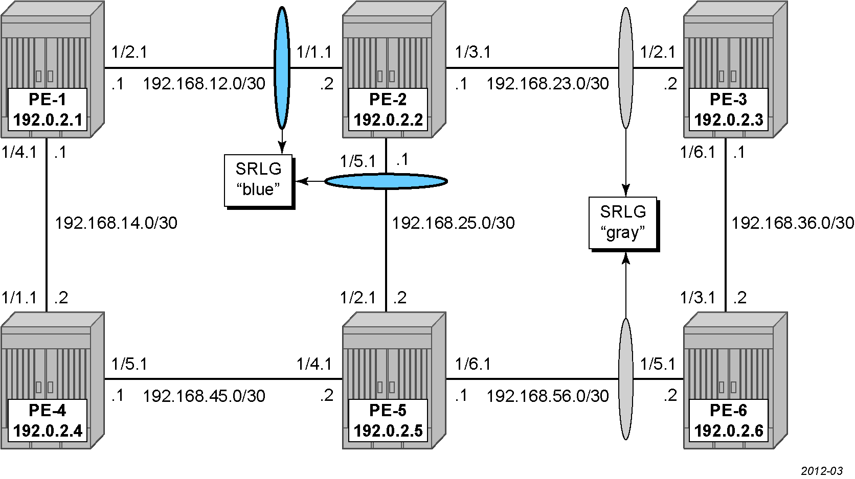
The configuration of the srlg-blue group is only mandatory on PE-1, PE-2, and PE-5, while the srlg-gray group is only mandatory on PE-2, PE-3, PE-5, and PE-6. However, it is good practice to configure both SRLG groups on all nodes, as follows:
# on all nodes:
    network-instance default {
        traffic-engineering {
            shared-risk-link-groups {
                group srlg-blue {
                    value 1
                }
                group srlg-gray {
                    value 2
                }
            }
The interfaces in the TE context need to be linked to the related SRLG group, which is a unidirectional indicator, applying only to the egress direction; therefore, it needs to be configured on both sides of the interface. For example on PE-1, the interface to PE-2 is part of the srlg-blue group. An interface can be part of multiple SRLG groups similar to the admin-group functionality. Admin groups are configured in parallel to indicate that both can be configured and can work independently.
# on PE-1:
    network-instance default {
        traffic-engineering {
            interface ethernet-1/2.1 {
                admin-group [
                    adm-green
                ]
                srlg-membership [
                    srlg-blue
                ]
            }
            interface ethernet-1/4.1 {
                admin-group [
                    adm-red
                ]
            }
On PE-2, the following SRLGs and admin groups are linked to the interfaces.
# on PE-2:
    network-instance default {
        traffic-engineering {
            interface ethernet-1/1.1 {
                admin-group [
                    adm-green
                ]
                srlg-membership [
                    srlg-blue
                ]
            }
            interface ethernet-1/3.1 {
                admin-group [
                    adm-green
                ]
                srlg-membership [
                    srlg-gray
                ]
            }
            interface ethernet-1/5.1 {
                srlg-membership [
                    srlg-blue
                ]
            }
The configuration on the other nodes is similar.
The SRLG configuration can be verified using the following commands. The SRLG groups on PE-1 are the following:
+-----------------------------------------------------+-----------------------------------------------------+------------+
|                  Network-instance                   |                        Name                         |   Value    |
+=====================================================+=====================================================+============+
| default                                             | srlg-blue                                           |          1 |
| default                                             | srlg-gray                                           |          2 |
+-----------------------------------------------------+-----------------------------------------------------+------------+
In the following list of TE interfaces on PE-2, admin groups and SRLG membership are indicated:
--{ + running }--[  ]--
A:admin@PE-2# info from state / network-instance default traffic-engineering interface * | as table | filter fields *

+------------+------------+-----------+------------+------------+-------------------------+----------------------------+
|  Network-  | Interface- | Te-metric |   Admin-   |   Srlg-    | Interface-ref interface | Interface-ref subinterface |
|  instance  |    name    |           |   group    | membership |                         |                            |
+============+============+===========+============+============+=========================+============================+
| default    | ethernet-  |           | adm-green  | srlg-blue  | ethernet-1/1            |                          1 |
|            | 1/1.1      |           |            |            |                         |                            |
| default    | ethernet-  |           | adm-green  | srlg-gray  | ethernet-1/3            |                          1 |
|            | 1/3.1      |           |            |            |                         |                            |
| default    | ethernet-  |           |            | srlg-blue  | ethernet-1/5            |                          1 |
|            | 1/5.1      |           |            |            |                         |                            |
+------------+------------+-----------+------------+------------+-------------------------+----------------------------+
Standby or secondary path with SRLG constraint
SRLG groups can be constraints to set up a standby path. The following uncolored SR-MPLS TE policy with an unconstrained primary path and a standby path with SRLG restriction is configured on PE-1:
# on PE-1:
    network-instance default {
        traffic-engineering-policies {
            policy pol-PE-1-PE-2_standby-srlg {
                policy-type sr-mpls-uncolored
                admin-state enable
                endpoint 192.0.2.2
                segment-list 12 {
                    admin-state enable
                    segment-list-type primary
                    dynamic {
                        path-algorithm local-cspf
                        te-constraints {
                            label-stack-reduction false   # optional; for verification purposes
                        }
                    }
                }
                segment-list 22 {
                    admin-state enable
                    segment-list-type standby           # or segment-list-type secondary
                    dynamic {
                        path-algorithm local-cspf
                        te-constraints {
                            label-stack-reduction false   # optional; for verification purposes
                            exclude-srlg [
                                srlg-blue
                            ]
                        }
                    }
                }
            }
The SRLG configuration for the standby or secondary path is similar. In this chapter, the standby path is chosen because the standby path is already computed and can be verified easily. The secondary path is only computed when no other path is operationally up.
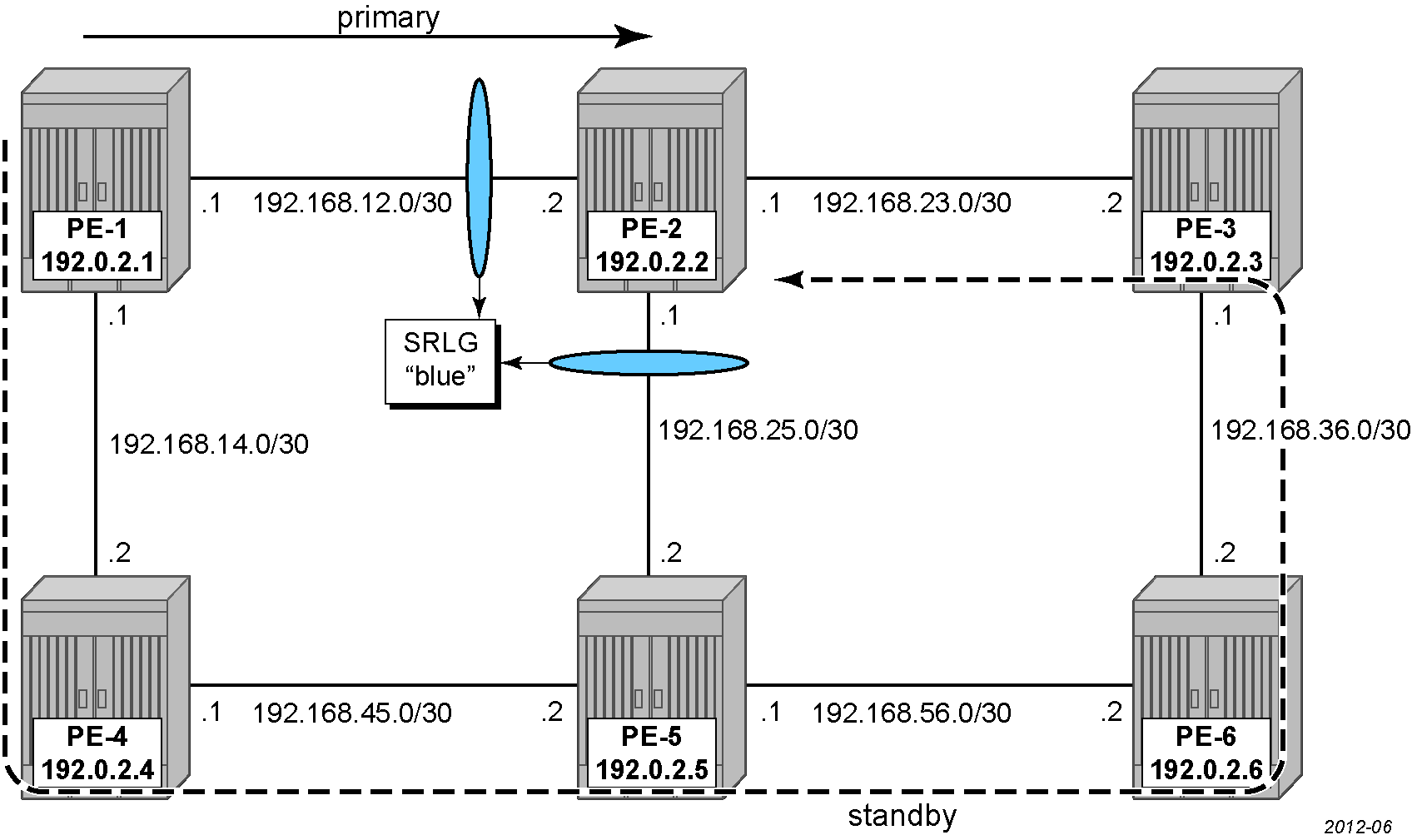
SRLG for standby path shows that the primary path follows the direct link from PE-1 to PE-2, while the standby path excludes the interfaces in srlg-blue, so it follows the dashed line from PE-1 over PE-4, PE-5, PE-6, and PE-3 to PE-2 instead of passing over the direct link between PE-5 and PE-2.
Both the primary and the standby segment lists are dynamic without any explicit hop. Without any constraint, PE-2 is only one hop away from PE-1 on the primary path. The following command shows the CSPF calculated hop in the primary path:
--{ + running }--[  ]--
A:admin@PE-1# info from state / network-instance default traffic-engineering-policies policy-database sr-uncolored policy
* protocol-origin local segment-list 12 computed-segments segment * | as table | filter fields *

+---------+---------+---------+---------+---------+---------+---------+---------+---------+---------+---------+---------+
| Network | Policy  | Policy  | Segment | Segment |  Hop-   |   Ip-   |   Is-   | Unnumbe | Router- |  Sid-   |  Sid-   |
| -instan | policy- | protoco |  -list  | -index  |  type   | address |  loose  | red-if- |   id    |  type   |  value  |
|   ce    |  name   |   l-    |         |         |         |         |         |   id    |         |         |  mpls-  |
|         |         | origin  |         |         |         |         |         |         |         |         |  label  |
+=========+=========+=========+=========+=========+=========+=========+=========+=========+=========+=========+=========+
| default | pol-PE- | local   |      12 |       1 | ipv4    | 192.168 | false   |         | 192.0.2 | adjacen |    2100 |
|         | 1-PE-   |         |         |         |         | .12.2   |         |         | .2      | cy-sid  |         |
|         | 2_stand |         |         |         |         |         |         |         |         |         |         |
|         | by-srlg |         |         |         |         |         |         |         |         |         |         |
---snip---
When the segment lists in the SR-MPLS uncolored TE policy are configured with dynamic te-constraints label-stack-reduction true (which is the default setting), the label stack is reduced to the node SID of the destination and no intermediate hops are shown.
The following command shows the CSPF calculated hops in the standby path: over PE-4, PE-5, PE-6, and PE-3 to destination PE-2.
--{ + running }--[  ]--
A:admin@PE-1# info from state / network-instance default traffic-engineering-policies policy-database sr-uncolored policy
* protocol-origin local segment-list 22 computed-segments segment * | as table | filter fields *

+---------+---------+---------+---------+---------+---------+---------+---------+---------+---------+---------+---------+
| Network | Policy  | Policy  | Segment | Segment |  Hop-   |   Ip-   |   Is-   | Unnumbe | Router- |  Sid-   |  Sid-   |
| -instan | policy- | protoco |  -list  | -index  |  type   | address |  loose  | red-if- |   id    |  type   |  value  |
|   ce    |  name   |   l-    |         |         |         |         |         |   id    |         |         |  mpls-  |
|         |         | origin  |         |         |         |         |         |         |         |         |  label  |
+=========+=========+=========+=========+=========+=========+=========+=========+=========+=========+=========+=========+
| default | pol-PE- | local   |      22 |       1 | ipv4    | 192.168 | false   |         | 192.0.2 | adjacen |    2101 |
|         | 1-PE-   |         |         |         |         | .14.2   |         |         | .4      | cy-sid  |         |
|         | 2_stand |         |         |         |         |         |         |         |         |         |         |
|         | by-srlg |         |         |         |         |         |         |         |         |         |         |
| default | pol-PE- | local   |      22 |       2 | ipv4    | 192.168 | false   |         | 192.0.2 | adjacen |    2101 |
|         | 1-PE-   |         |         |         |         | .45.2   |         |         | .5      | cy-sid  |         |
|         | 2_stand |         |         |         |         |         |         |         |         |         |         |
|         | by-srlg |         |         |         |         |         |         |         |         |         |         |
| default | pol-PE- | local   |      22 |       3 | ipv4    | 192.168 | false   |         | 192.0.2 | adjacen |    2102 |
|         | 1-PE-   |         |         |         |         | .56.2   |         |         | .6      | cy-sid  |         |
|         | 2_stand |         |         |         |         |         |         |         |         |         |         |
|         | by-srlg |         |         |         |         |         |         |         |         |         |         |
| default | pol-PE- | local   |      22 |       4 | ipv4    | 192.168 | false   |         | 192.0.2 | adjacen |    2100 |
|         | 1-PE-   |         |         |         |         | .36.1   |         |         | .3      | cy-sid  |         |
|         | 2_stand |         |         |         |         |         |         |         |         |         |         |
|         | by-srlg |         |         |         |         |         |         |         |         |         |         |
| default | pol-PE- | local   |      22 |       5 | ipv4    | 192.168 | false   |         | 192.0.2 | adjacen |    2100 |
|         | 1-PE-   |         |         |         |         | .23.1   |         |         | .2      | cy-sid  |         |
|         | 2_stand |         |         |         |         |         |         |         |         |         |         |
|         | by-srlg |         |         |         |         |         |         |         |         |         |         |
---snip---
Another way to verify the segments in the standby segment list 22, is the following OAM lsp-trace command where segment-list-index 22 corresponds to the standby path:
# on PE-1:
--{ + running }--[  ]--
A:admin@PE-1# tools oam lsp-trace te-policy sr-uncolored policy pol-PE-1-PE-2_standby-srlg protocol-origin local segment-list-index 22
/:
Initiated LSP Trace for TE-policy pol-PE-1-PE-2_standby-srlg with session id 49177.
Please check "info from state oam" for result
The following shows the result of the preceding tools oam lsp-trace command:
--{ + running }--[  ]--
A:admin@PE-1# info from state oam lsp-trace te-policy sr-uncolored policy pol-PE-1-PE-2_standby-srlg protocol-origin local session-id 49177
    test-active false
    path-destination {
        ip-address 127.0.0.1
    }
    hop 1 {
        probe 1 {
            probe-size 220
            probes-sent 1
            reply {
                received true
                reply-sender 192.0.2.4
                udp-data-length 32
                mpls-ttl 1
                round-trip-time 4882
                return-code replying-router-is-egress-for-fec-at-stack-depth-n
                return-subcode 5
            }
        }
        probe 2 {
            probe-size 188
            probes-sent 1
            reply {
                received true
                reply-sender 192.0.2.4
                udp-data-length 72
                mpls-ttl 1
                round-trip-time 62860
                return-code label-switched-at-stack-depth-n
                return-subcode 4
            }
            downstream-detailed-mapping 1 {
                mtu 1500
                address-type ipv4-numbered
                downstream-router-address 192.168.45.2
                downstream-interface-address 192.168.45.2
                mpls-label 1 {
                    label IMPLICIT_NULL
                    protocol isis
                }
                mpls-label 2 {
                    label 2102
                    protocol isis
                }
                mpls-label 3 {
                    label 2100
                    protocol isis
                }
                mpls-label 4 {
                    label 2100
                    protocol isis
                }
            }
        }
    }
    hop 2 {
        probe 1 {
            probe-size 188
            probes-sent 1
            reply {
                received true
                reply-sender 192.0.2.5
                udp-data-length 32
                mpls-ttl 2
                round-trip-time 45874
                return-code replying-router-is-egress-for-fec-at-stack-depth-n
                return-subcode 4
            }
        }
        probe 2 {
            probe-size 156
            probes-sent 1
            reply {
                received true
                reply-sender 192.0.2.5
                udp-data-length 68
                mpls-ttl 2
                round-trip-time 45810
                return-code label-switched-at-stack-depth-n
                return-subcode 3
            }
            downstream-detailed-mapping 1 {
                mtu 1500
                address-type ipv4-numbered
                downstream-router-address 192.168.56.2
                downstream-interface-address 192.168.56.2
                mpls-label 1 {
                    label IMPLICIT_NULL
                    protocol isis
                }
                mpls-label 2 {
                    label 2100
                    protocol isis
                }
                mpls-label 3 {
                    label 2100
                    protocol isis
                }
            }
        }
    }
    hop 3 {
        probe 1 {
            probe-size 156
            probes-sent 1
            reply {
                received true
                reply-sender 192.0.2.6
                udp-data-length 32
                mpls-ttl 3
                round-trip-time 49904
                return-code replying-router-is-egress-for-fec-at-stack-depth-n
                return-subcode 3
            }
        }
        probe 2 {
            probe-size 124
            probes-sent 1
            reply {
                received true
                reply-sender 192.0.2.6
                udp-data-length 64
                mpls-ttl 3
                round-trip-time 43918
                return-code label-switched-at-stack-depth-n
                return-subcode 2
            }
            downstream-detailed-mapping 1 {
                mtu 1500
                address-type ipv4-numbered
                downstream-router-address 192.168.36.1
                downstream-interface-address 192.168.36.1
                mpls-label 1 {
                    label IMPLICIT_NULL
                    protocol isis
                }
                mpls-label 2 {
                    label 2100
                    protocol isis
                }
            }
        }
    }
    hop 4 {
        probe 1 {
            probe-size 124
            probes-sent 1
            reply {
                received true
                reply-sender 192.0.2.3
                udp-data-length 32
                mpls-ttl 4
                round-trip-time 8869
                return-code replying-router-is-egress-for-fec-at-stack-depth-n
                return-subcode 2
            }
        }
        probe 2 {
            probe-size 92
            probes-sent 1
            reply {
                received true
                reply-sender 192.0.2.3
                udp-data-length 60
                mpls-ttl 4
                round-trip-time 42864
                return-code label-switched-at-stack-depth-n
                return-subcode 1
            }
            downstream-detailed-mapping 1 {
                mtu 1500
                address-type ipv4-numbered
                downstream-router-address 192.168.23.1
                downstream-interface-address 192.168.23.1
                mpls-label 1 {
                    label IMPLICIT_NULL
                    protocol isis
                }
            }
        }
    }
    hop 5 {
        probe 1 {
            probe-size 92
            probes-sent 1
            reply {
                received true
                reply-sender 192.0.2.2
                udp-data-length 32
                mpls-ttl 5
                round-trip-time 7868
                return-code replying-router-is-egress-for-fec-at-stack-depth-n
                return-subcode 1
            }
        }
    }
Both primary and standby path with SRLG constraint
SRLG groups can be constraints to set up a primary as well as a standby path. The following SR-MPLS uncolored TE policy on PE-1 has a primary path that excludes srlg-blue and a standby path configured with secondary-srlg true:
# on PE-1:
    network-instance default {
        traffic-engineering-policies {
            policy pol-PE-1-PE-2_excl-standby-srlg {
                policy-type sr-mpls-uncolored
                admin-state enable
                endpoint 192.0.2.2
                segment-list 13 {
                    admin-state enable
                    segment-list-type primary
                    dynamic {
                        path-algorithm local-cspf
                        te-constraints {
                            label-stack-reduction false
                            exclude-srlg [
                                srlg-blue
                            ]
                        }
                    }
                }
                segment-list 23 {
                    admin-state enable
                    segment-list-type standby
                    dynamic {
                        path-algorithm local-cspf
                        te-constraints {
                            label-stack-reduction false
                            secondary-srlg true
                        }
                    }
                }
            }
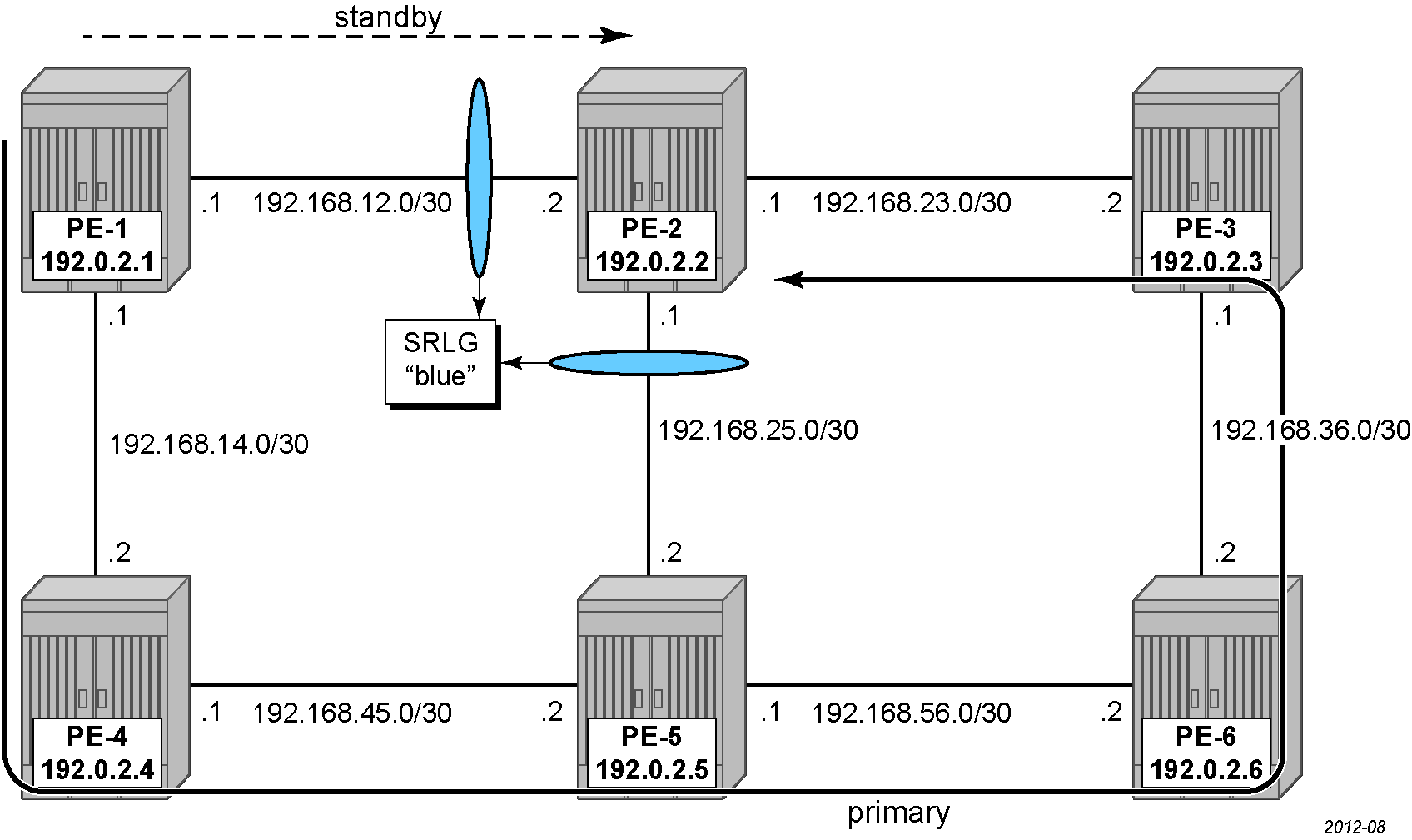
In the segment list for the standby path, the secondary-srlg true setting tells CSPF to avoid SRLGs used by the primary segment-list when computing this segment list, ensuring SRLG disjointness. Therefore, when the primary path excludes srlg-blue, the links in srlg-blue can be used by the standby path, so the reverse situation may occur where the primary path is longer caused by a constraint that the standby path does not have, as shown in Primary path with exclude-srlg and standby path with secondary-srlg.
The secondary-srlg command has no effect on a secondary non-standby segment list. As soon as the primary path goes operationally down, the primary path and its attributes are deleted, so no information can be retrieved in runtime.
The primary path has the constraint not to use any TE interfaces in srlg-blue and is represented by the dashed line from PE-1 over PE-4, PE-5, PE-6, and PE-3 to PE-2, while the standby path has the constraint not to use any interfaces in an SRLG used by the primary path and it takes the direct link from PE-1 to PE-2.
Both the primary and the standby segment lists are dynamic without any explicit hop. With the constraint not to use srlg-blue, PE-2 is five hops away from PE-1 on the primary path. The following command shows the CSPF calculated hop in the primary path with segment list 13:
--{ + running }--[  ]--
A:admin@PE-1# info from state / network-instance default traffic-engineering-policies policy-database sr-uncolored policy
* protocol-origin local segment-list 13 computed-segments segment * | as table | filter fields *

+---------+---------+---------+---------+---------+---------+---------+---------+---------+---------+---------+---------+
| Network | Policy  | Policy  | Segment | Segment |  Hop-   |   Ip-   |   Is-   | Unnumbe | Router- |  Sid-   |  Sid-   |
| -instan | policy- | protoco |  -list  | -index  |  type   | address |  loose  | red-if- |   id    |  type   |  value  |
|   ce    |  name   |   l-    |         |         |         |         |         |   id    |         |         |  mpls-  |
|         |         | origin  |         |         |         |         |         |         |         |         |  label  |
+=========+=========+=========+=========+=========+=========+=========+=========+=========+=========+=========+=========+
| default | pol-PE- | local   |      13 |       1 | ipv4    | 192.168 | false   |         | 192.0.2 | adjacen |    2101 |
|         | 1-PE-   |         |         |         |         | .14.2   |         |         | .4      | cy-sid  |         |
|         | 2_excl- |         |         |         |         |         |         |         |         |         |         |
|         | standby |         |         |         |         |         |         |         |         |         |         |
|         | -srlg   |         |         |         |         |         |         |         |         |         |         |
| default | pol-PE- | local   |      13 |       2 | ipv4    | 192.168 | false   |         | 192.0.2 | adjacen |    2101 |
|         | 1-PE-   |         |         |         |         | .45.2   |         |         | .5      | cy-sid  |         |
|         | 2_excl- |         |         |         |         |         |         |         |         |         |         |
|         | standby |         |         |         |         |         |         |         |         |         |         |
|         | -srlg   |         |         |         |         |         |         |         |         |         |         |
| default | pol-PE- | local   |      13 |       3 | ipv4    | 192.168 | false   |         | 192.0.2 | adjacen |    2102 |
|         | 1-PE-   |         |         |         |         | .56.2   |         |         | .6      | cy-sid  |         |
|         | 2_excl- |         |         |         |         |         |         |         |         |         |         |
|         | standby |         |         |         |         |         |         |         |         |         |         |
|         | -srlg   |         |         |         |         |         |         |         |         |         |         |
| default | pol-PE- | local   |      13 |       4 | ipv4    | 192.168 | false   |         | 192.0.2 | adjacen |    2100 |
|         | 1-PE-   |         |         |         |         | .36.1   |         |         | .3      | cy-sid  |         |
|         | 2_excl- |         |         |         |         |         |         |         |         |         |         |
|         | standby |         |         |         |         |         |         |         |         |         |         |
|         | -srlg   |         |         |         |         |         |         |         |         |         |         |
| default | pol-PE- | local   |      13 |       5 | ipv4    | 192.168 | false   |         | 192.0.2 | adjacen |    2100 |
|         | 1-PE-   |         |         |         |         | .23.1   |         |         | .2      | cy-sid  |         |
|         | 2_excl- |         |         |         |         |         |         |         |         |         |         |
|         | standby |         |         |         |         |         |         |         |         |         |         |
|         | -srlg   |         |         |         |         |         |         |         |         |         |         |
---snip---
The following command shows the CSPF calculated hops in the standby path with segment list 23: over the direct link from PE-1 to destination PE-2.
--{ + running }--[  ]--
A:admin@PE-1# info from state / network-instance default traffic-engineering-policies policy-database sr-uncolored policy
* protocol-origin local segment-list 23 computed-segments segment * | as table | filter fields *

+---------+---------+---------+---------+---------+---------+---------+---------+---------+---------+---------+---------+
| Network | Policy  | Policy  | Segment | Segment |  Hop-   |   Ip-   |   Is-   | Unnumbe | Router- |  Sid-   |  Sid-   |
| -instan | policy- | protoco |  -list  | -index  |  type   | address |  loose  | red-if- |   id    |  type   |  value  |
|   ce    |  name   |   l-    |         |         |         |         |         |   id    |         |         |  mpls-  |
|         |         | origin  |         |         |         |         |         |         |         |         |  label  |
+=========+=========+=========+=========+=========+=========+=========+=========+=========+=========+=========+=========+
| default | pol-PE- | local   |      23 |       1 | ipv4    | 192.168 | false   |         | 192.0.2 | adjacen |    2100 |
|         | 1-PE-   |         |         |         |         | .12.2   |         |         | .2      | cy-sid  |         |
|         | 2_excl- |         |         |         |         |         |         |         |         |         |         |
|         | standby |         |         |         |         |         |         |         |         |         |         |
|         | -srlg   |         |         |         |         |         |         |         |         |         |         |
---snip---
Conclusion
Interpreting the SRLG information in the TE database makes it possible to protect an LSP even when multiple TE interfaces fail as a result of an underlying transmission failure.
SRLGs can be a constraint for standby or secondary paths of an unconstrained primary path or SRLGs can be a constraint for primary and standby paths where the primary path avoids the SRLG and the standby path computes its segment list so that it avoids the SRLGs used by the primary path.