Segment Routing – Traffic Engineered Tunnels
This chapter provides information about Segment Routing – Traffic Engineered Tunnels.
Topics in this chapter include:
Applicability
The CLI in the current edition corresponds to SR Linux Release 25.10.R2.
Overview
Segment Routing (SR) is described in the Segment Routing with IS-IS Control Plane chapter, where the advertisement of node prefix segment identifiers (SIDs) cause the automatic creation of ECMP-aware shortest path MPLS tunnels on each SR-aware router. Each node prefix SID is a globally unique value and becomes an MPLS label in the MPLS data plane. The label is advertised and learned by each SR-capable router using control plane extensions to the IS-IS protocol.
It is also possible to create source-routed traffic-engineered (TE) end-to-end segment routing paths, where routing constraints such as strict or loose hops can be used to determine a data path to be taken through a network.
These SR-TE Label Switched Paths (LSPs) are implemented as uncolored SR-MPLS TE policies. The path can be computed locally by the head-end PE or by offloading the path computation to an external controller. The intermediate and tail-end router are unaware of the presence of an SR-TE LSP because there is no signaling protocol used to create the path. If a packet is forwarded through the SR tunnel, each router along the path reads the top label and forwards the packet according to the SR tunnel table entry for that label.
This chapter describes the configuration of uncolored SR-MPLS TE policies with locally-computed source-routed paths and how they can be used in the data plane of Layer 2 and Layer 3 services. In the cases described, an uncolored SR-MPLS TE policy containing an explicit path with a number of strict or loose hops is created at the head-end router and used to construct an SR-TE LSP by translating the IP addresses configured in the MPLS path to a SID. This results in an MPLS path with state at the head end only, comprising a stack of SIDs, where each SID is an MPLS label.
In this chapter, IS-IS is used to advertise the SIDs and a set of extensions to IS-IS have been defined, which require additional configuration on each network router.
The LSP is instantiated—the state is operationally "up"—and a tunnel table entry is created that is owned by the te-policy-sr-mpls-uncolored protocol. Any data packet that is resolved to use the resulting tunnel has the label stack imposed at the head-end router and is forwarded out of the appropriate next-hop interface. This interface is determined by the topmost label in the stack.
If the label is a node SID, the outgoing interface is determined by the IGP—the shortest path to the router that the node SID represents.
If the label is a local adjacency SID, the outgoing interface is the local interface for which this SID is generated by the IGP.
The segments referenced can be a prefix segment, such as a node segment or an adjacency segment, which represents a specific adjacency between two nodes. The SIDs are used as MPLS labels.
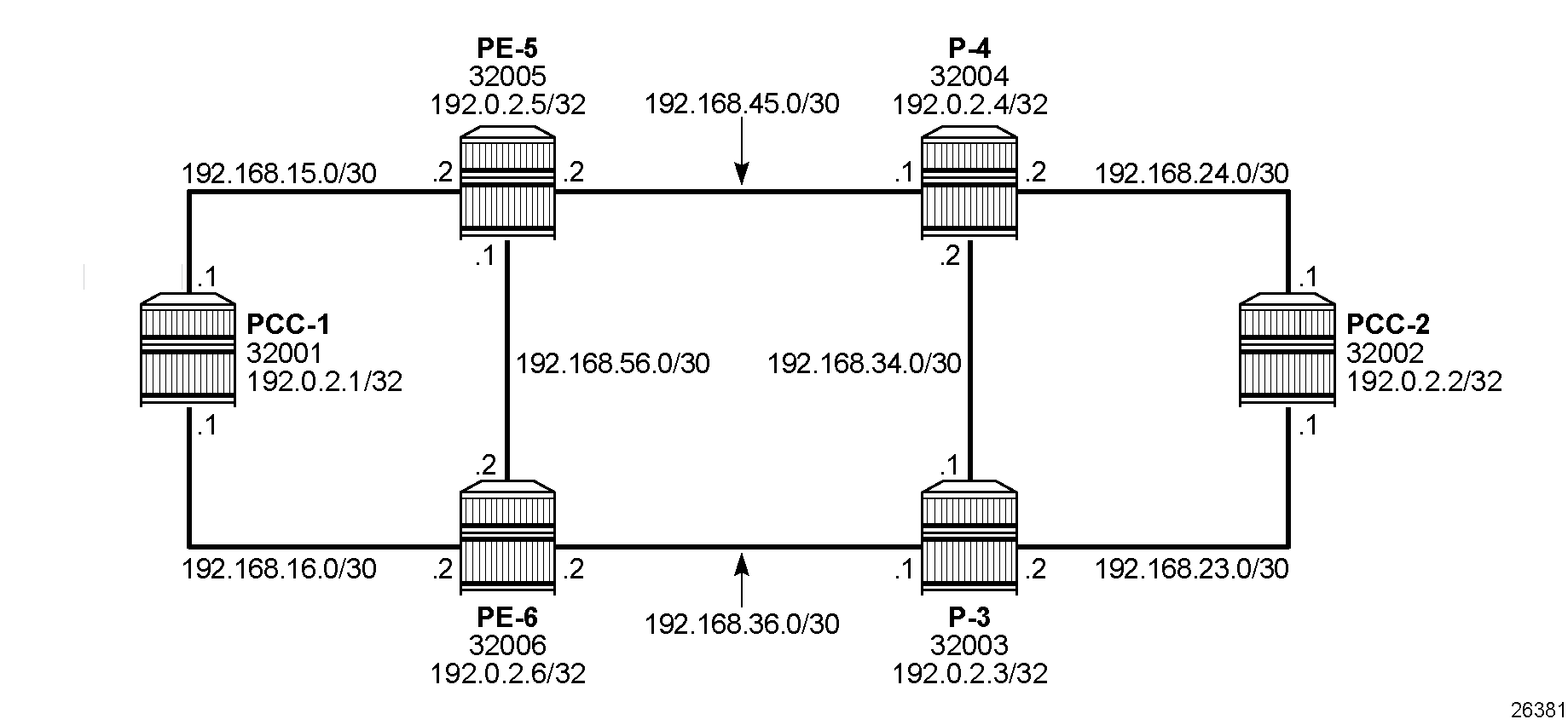
In the following configuration examples, the LSP path is created at the head-end router, and computed by translating a list of hops containing IP addresses into a list of SIDs, by examining the IS-IS TE database. The head-end router is referred to as a Path Computation Client (PCC). Segment routing network schematic shows the example topology used, and a pair of bidirectional connected SR-TE LSPs between PCC-1 and PCC-2 is configured to illustrate SR-TE LSPs. All interfaces between PCC-1 and its neighbors have the IS-IS metric set to 100. Similarly, for PCC-2, the IGP metric is also set to 100 between itself and its neighbors. The IS-IS metric on router interfaces between the core routers P-3, P-4, PE-5, and PE-6 is 10.
Configuration
MPLS label ranges
MPLS label ranges for adjacency SIDs and node SIDs must be configured. The Segment Routing Global Block (SRGB) is the MPLS label range from which node SIDs are allocated. The Segment Routing Local Block (SRLB) is the MPLS label range from which dynamic adjacency SIDs are allocated. In this example, a range of 1000 labels is chosen for the SRGB and another range of 1000 labels is chosen for the SRLB. For operational simplicity, Nokia recommends that the same MPLS label ranges are chosen for each SR-capable router. However, this is not an explicit requirement. On all nodes, the SRGB and SRLB are configured as follows:
# on all nodes:
enter candidate
    system {
        mpls {
            label-ranges {
                static srgb-static-mpls {            # SRGB for node SIDs
                    shared true
                    start-label 32000
                    end-label 32999
                }
                dynamic srlb-dynamic-mpls {          # SRLG for adjacency SIDs
                    start-label 525000
                    end-label 525999
                }
When the SRGB and SRLB label ranges have been configured, the MPLS label ranges can be verified as follows:
--{ + running }--[  ]--
A:admin@PCC-1# info from state with-context / system mpls label-ranges static * | as table | filter fields *

+-----------------------------------------+--------+-------------+-----------+------------------+-------------+----------------+
|                  Name                   | Shared | Start-label | End-label | Allocated-labels | Free-labels |     Status     |
+=========================================+========+=============+===========+==================+=============+================+
| srgb-static-mpls                        | true   |       32000 |     32999 |                0 |        1000 | ready          |
+-----------------------------------------+--------+-------------+-----------+------------------+-------------+----------------+

--{ + running }--[  ]--
A:admin@PCC-1# info from state with-context / system mpls label-ranges dynamic * | as table | filter fields *

+--------------------------------------------------+-------------+-----------+------------------+-------------+----------------+
|                       Name                       | Start-label | End-label | Allocated-labels | Free-labels |     Status     |
+==================================================+=============+===========+==================+=============+================+
| srlb-dynamic-mpls                                |      525000 |    525999 |                0 |        1000 | ready          |
+--------------------------------------------------+-------------+-----------+------------------+-------------+----------------+
SR-ISIS configuration
The first step is to configure a single-level IS-IS instance on each router, as follows:
# on PCC-1:
    network-instance default {
        protocols {
            isis {
                instance 0 {
                    admin-state enable
                    level-capability L2
                    net [
                        49.0000.1920.0000.2001.00
                    ]
                    interface ethernet-1/5.1 {
                        admin-state enable
                        circuit-type point-to-point
                        level 2 {
                            metric 100
                        }
                    }
                    interface ethernet-1/6.1 {
                        admin-state enable
                        circuit-type point-to-point
                        level 2 {
                            metric 100
                        }
                    }
                    interface system0.0 {
                    }
                    level 2 {
                    }
                }
The configuration for all other nodes is similar, with different values for net, interfaces, and IGP metrics, as can be derived from Segment routing network schematic.
For each router to be segment-routing capable, additional configuration is required. On PCC-1, segment routing is configured as follows:
# on PCC-1:
    network-instance default {
         protocols {
            isis {
                dynamic-label-block srlb-dynamic-mpls       ## SRLB for adj SIDs
                instance 0 {
                    segment-routing {
                        mpls {
                            dynamic-adjacency-sids {
                                all-interfaces true
                            }
                        }
                    }
                }
            }
        }
        segment-routing {
            mpls {
                global-block {
                    label-range srgb-static-mpls            ## SRGB for node SIDs
                }
                local-prefix-sid 1 {
                    interface system0.0
                    ipv4-label-index 1        ## index 2 on PCC-2, 3 on P-3, 4 on P-4...
                    node-sid true
                }
The node SID is manually configured as an index. With the SRGB label base equal to 32000 and the IPv4 label index 1 on PCC-1, the node SID for PCC-1 is 32000 + 1 = 32001.
The following output taken from PCC-1 shows the prefix SIDs configured on the routers in the network and advertised using IS-IS.
--{ + running }--[  ]--
A:admin@PCC-1# info from state network-instance default segment-routing mpls sid-database

    prefix-sid 192.0.2.1/32 sid-label-value 32001 protocol direct protocol-instance 0 protocol-multi-topology 0 algorithm 0 {
        active true
    }
    prefix-sid 192.0.2.2/32 sid-label-value 32002 protocol isis protocol-instance 0 protocol-multi-topology 0 algorithm 0 {
        active true
    }
    prefix-sid 192.0.2.3/32 sid-label-value 32003 protocol isis protocol-instance 0 protocol-multi-topology 0 algorithm 0 {
        active true
    }
    prefix-sid 192.0.2.4/32 sid-label-value 32004 protocol isis protocol-instance 0 protocol-multi-topology 0 algorithm 0 {
        active true
    }
    prefix-sid 192.0.2.5/32 sid-label-value 32005 protocol isis protocol-instance 0 protocol-multi-topology 0 algorithm 0 {
        active true
    }
    prefix-sid 192.0.2.6/32 sid-label-value 32006 protocol isis protocol-instance 0 protocol-multi-topology 0 algorithm 0 {
        active true
    }
The output is similar for all routers in the network.
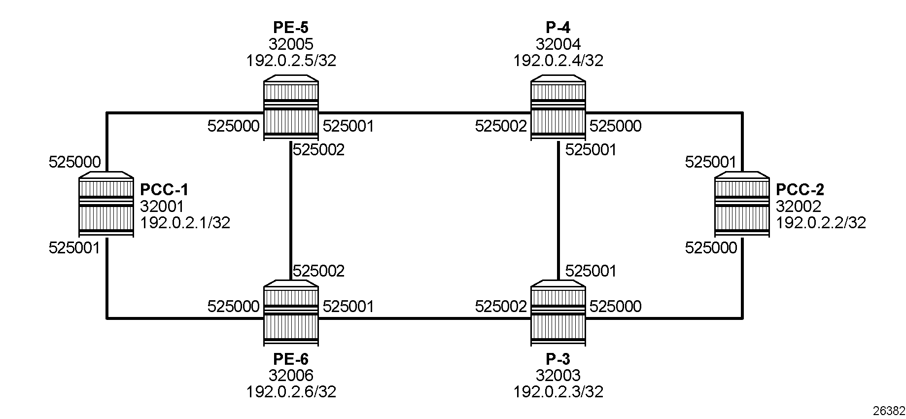
Adjacency SIDs are assigned to each interface link.
The following tunnel table shows 7 SR-ISIS tunnels: one to each other system IP prefix with tunnel ID equal to the node SID and one to each adjacency with tunnel ID equal to the adjacency SID. For each destination prefix, the tunnel table indicates the next hop and the interface via which it is reached, as well as the end-to-end metric for the tunnel.
--{ + running }--[  ]--
A:admin@PCC-1# show network-instance default tunnel-table ipv4

-------------------------------------------------------------------------------------------------------------------------------------------------------------------------------------------------------
IPv4 tunnel table of network-instance "default"
-------------------------------------------------------------------------------------------------------------------------------------------------------------------------------------------------------
+-----------------------------------+----------------+----------+-----+----------+---------+--------------------------+----------------------+----------------------+---------------------------------+
|            IPv4 Prefix            |  Tunnel Type   |  Tunnel  | FIB |  Metric  | Prefere |       Last Update        |   Backup Nexthops    |   Next-hop (Type)    |            Next-hop             |
|                                   |                |    ID    |     |          |   nce   |                          |                      |                      |                                 |
+===================================+================+==========+=====+==========+=========+==========================+======================+======================+=================================+
| 192.0.2.2/32                      | sr-isis        | 32002    | Y   | 210      | 11      | 2026-02-17T13:02:35.444Z |                      | 192.168.15.2 (mpls)  | ethernet-1/5.1                  |
| 192.0.2.3/32                      | sr-isis        | 32003    | Y   | 110      | 11      | 2026-02-17T13:02:42.972Z |                      | 192.168.16.2 (mpls)  | ethernet-1/6.1                  |
| 192.0.2.4/32                      | sr-isis        | 32004    | Y   | 110      | 11      | 2026-02-17T13:02:49.544Z |                      | 192.168.15.2 (mpls)  | ethernet-1/5.1                  |
| 192.0.2.5/32                      | sr-isis        | 32005    | Y   | 100      | 11      | 2026-02-17T13:02:56.175Z |                      | 192.168.15.2 (mpls)  | ethernet-1/5.1                  |
| 192.0.2.6/32                      | sr-isis        | 32006    | Y   | 100      | 11      | 2026-02-17T13:03:04.667Z |                      | 192.168.16.2 (mpls)  | ethernet-1/6.1                  |
| 192.168.15.2/32                   | sr-isis        | 525000   | Y   | 0        | 11      | 2026-02-17T12:51:42.019Z |                      | 192.168.15.2 (mpls)  | ethernet-1/5.1                  |
| 192.168.16.2/32                   | sr-isis        | 525001   | Y   | 0        | 11      | 2026-02-17T12:51:42.019Z |                      | 192.168.16.2 (mpls)  | ethernet-1/6.1                  |
+-----------------------------------+----------------+----------+-----+----------+---------+--------------------------+----------------------+----------------------+---------------------------------+
-------------------------------------------------------------------------------------------------------------------------------------------------------------------------------------------------------
7 SR-ISIS tunnels, 7 active, 0 inactive
-------------------------------------------------------------------------------------------------------------------------------------------------------------------------------------------------------
On PCC-1, the adjacency SID for the interface toward PE-5 is 525000, and the adjacency SID for the interface toward PE-6 is 525001.
An overview of the SIDs for the whole network is shown in Node and adjacency SIDs.
Uncolored SR-MPLS TE policies
This section describes uncolored SR-MPLS TE policies that are configured on the head-end router (the PCC). The path taken through the network is computed locally by the PCC. To influence the path taken, a series of strict and loose hops is configured in an MPLS path.
SR-TE LSPs configured without an explicit path is effectively a shortest path tunnel to the destination node. The destination address is resolved to the node SID of the tail-end router.
Traffic engineering must be configured on the nodes. The TE configuration on PCC-1 is as follows:
# on PCC-1:
    network-instance default {
        protocols {
            isis {
                instance 0 {
                    admin-state enable
                    te-database-install {
                    }
                    traffic-engineering {
                        advertisement true
                        legacy-link-attribute-advertisement false
                        ipv4-te-router-id 192.0.2.1
                    }
                }
            }
        }
        traffic-engineering {
            ipv4-te-router-id 192.0.2.1
            interface ethernet-1/5.1 {
                interface-ref {
                    interface ethernet-1/5
                    subinterface 1
                }
            }
            interface ethernet-1/6.1 {
                interface-ref {
                    interface ethernet-1/6
                    subinterface 1
                }
            }
The TE configuration on the other nodes is similar, with different router ID and interfaces.
PCC-initiated and computed LSP – explicit path with strict hops
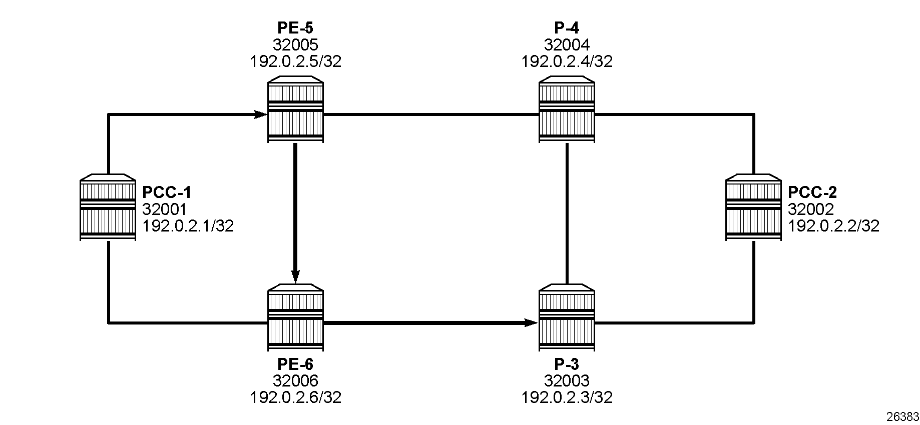
Consider an uncolored SR-MPLS TE policy configured on PCC-1, with tail end at PCC-2. Assume there is a requirement for the LSP to avoid the link from PE-5 to P-4 during normal working, so a strict path from PCC-1 via PE-5 to PE-6, and then on to P-3 is required before being forwarded to PCC-2. This is shown in Explicit path with strict hops from PCC-1 to PCC-2.
To meet these requirements, an explicit path is configured containing the following strict hops, using the system addresses to identify the hops. The following configures an uncolored SR-MPLS TE policy using the explicit path:
# on PCC-1:
    network-instance default {
        traffic-engineering-policies {
            explicit-paths {
                path PCC-controlled-strict-path {
                    hop 10 {
                        ip {
                            ip-address 192.0.2.5
                            hop-type strict
                        }
                    }
                    hop 20 {
                        ip {
                            ip-address 192.0.2.6
                            hop-type strict
                        }
                    }
                    hop 30 {
                        ip {
                            ip-address 192.0.2.3
                            hop-type strict
                        }
                    }
                }
            }
            policy pol_strict-to-PCC-2 {
                policy-type sr-mpls-uncolored
                admin-state enable
                endpoint 192.0.2.2
                segment-list 1 {
                    admin-state enable
                    explicit-path PCC-controlled-strict-path
                    segment-list-type primary
                }
            }
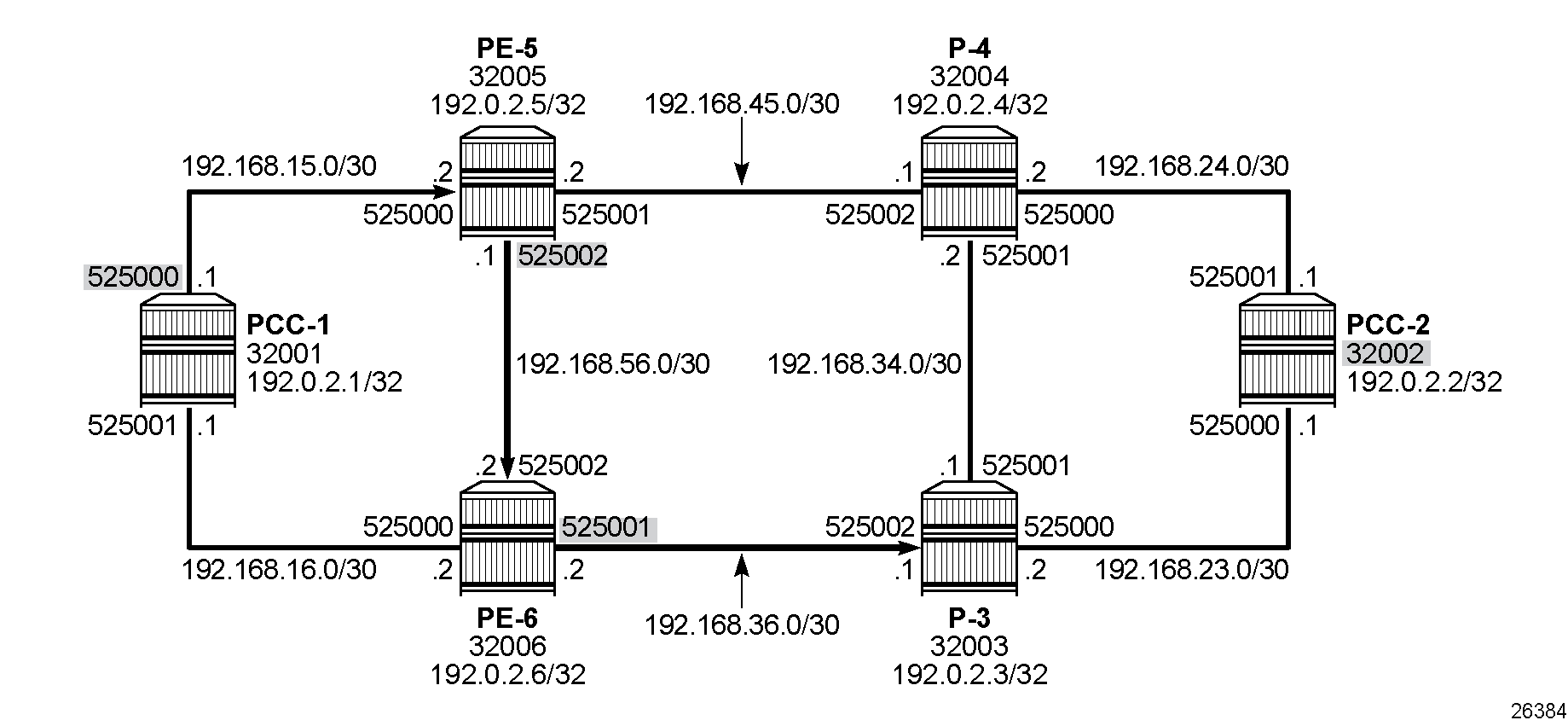
The following shows the segments in segment list 1 of the uncolored SR-MPLS TE policy "pol_strict-to-PCC-2" with adjacency SIDs for the three strict hops in the explicit path and a node SID for the loose hop to the destination hop of 192.0.2.2:
--{ + running }--[  ]--
A:admin@PCC-1# info from state / network-instance default traffic-engineering-policies policy-database sr-uncolored policy * protocol-origin local segment-list 1 computed-segments segment * | as table | filter fields ip-address router-id is-loose sid-type sid-value/mpls-label

+----------------------+----------------------+------------------------+--------------+---------------+----------------------+----------------------+----------+----------------+----------------------+
|   Network-instance   |  Policy policy-name  | Policy protocol-origin | Segment-list | Segment-index |      Ip-address      |      Router-id       | Is-loose |    Sid-type    | Sid-value mpls-label |
+======================+======================+========================+==============+===============+======================+======================+==========+================+======================+
| default              | pol_strict-to-PCC-2  | local                  |            1 |             1 | 192.168.15.2         | 192.0.2.5            | false    | adjacency-sid  |               525000 |
| default              | pol_strict-to-PCC-2  | local                  |            1 |             2 | 192.168.56.2         | 192.0.2.6            | false    | adjacency-sid  |               525002 |
| default              | pol_strict-to-PCC-2  | local                  |            1 |             3 | 192.168.36.1         | 192.0.2.3            | false    | adjacency-sid  |               525001 |
| default              | pol_strict-to-PCC-2  | local                  |            1 |             4 | 192.0.2.2            | 192.0.2.2            | true     | node-sid       |                32002 |
+----------------------+----------------------+------------------------+--------------+---------------+----------------------+----------------------+----------+----------------+----------------------+
The head-end router PCC-1 uses the SIDs as MPLS labels. The node SIDs and adjacency SIDs are shown in PCC computed segment list hop-to-label translation.
When the uncolored SR-MPLS TE policy is connected, the Tunnel Table Manager (TTM) adds an entry of type te-policy-sr-mpls-uncolored. This tunnel is available for the provisioning of services that use the TTM. The following output shows the tunnel table for PCC-1, which includes the shortest-path tunnels to all other routers in the network, plus the entry for the provisioned uncolored SR-MPLS TE policy. The default preference for an uncolored SR-MPLS TE policy in the tunnel table is 8.
--{ + running }--[  ]--
A:admin@PCC-1# show network-instance default tunnel-table ipv4

--------------------------------------------------------------------------------------------------------------------------------------------------------------------------------------------------------------------------------------
IPv4 tunnel table of network-instance "default"
--------------------------------------------------------------------------------------------------------------------------------------------------------------------------------------------------------------------------------------
+-------------------------------------------+----------------+----------+-----+----------+---------+--------------------------+--------------------------+--------------------------+------------------------------------------------+
|                IPv4 Prefix                |  Tunnel Type   |  Tunnel  | FIB |  Metric  | Prefere |       Last Update        |     Backup Nexthops      |     Next-hop (Type)      |                    Next-hop                    |
|                                           |                |    ID    |     |          |   nce   |                          |                          |                          |                                                |
+===========================================+================+==========+=====+==========+=========+==========================+==========================+==========================+================================================+
| 192.0.2.2/32                              | sr-isis        | 32002    | Y   | 210      | 11      | 2026-02-17T13:02:35.444Z |                          | 192.168.15.2 (mpls)      | ethernet-1/5.1                                 |
| 192.0.2.2/32                              | te-policy-sr-  | 1        | Y   | 220      | 8       | 2026-02-17T13:15:17.526Z |                          | 192.168.15.2/32 (sr-     | ethernet-1/5.1                                 |
|                                           | mpls-uncolored |          |     |          |         |                          |                          | isis)                    |                                                |
| 192.0.2.3/32                              | sr-isis        | 32003    | Y   | 110      | 11      | 2026-02-17T13:02:42.972Z |                          | 192.168.16.2 (mpls)      | ethernet-1/6.1                                 |
| 192.0.2.4/32                              | sr-isis        | 32004    | Y   | 110      | 11      | 2026-02-17T13:02:49.544Z |                          | 192.168.15.2 (mpls)      | ethernet-1/5.1                                 |
| 192.0.2.5/32                              | sr-isis        | 32005    | Y   | 100      | 11      | 2026-02-17T13:02:56.175Z |                          | 192.168.15.2 (mpls)      | ethernet-1/5.1                                 |
| 192.0.2.6/32                              | sr-isis        | 32006    | Y   | 100      | 11      | 2026-02-17T13:03:04.667Z |                          | 192.168.16.2 (mpls)      | ethernet-1/6.1                                 |
| 192.168.15.2/32                           | sr-isis        | 525000   | Y   | 0        | 11      | 2026-02-17T12:51:42.019Z |                          | 192.168.15.2 (mpls)      | ethernet-1/5.1                                 |
| 192.168.16.2/32                           | sr-isis        | 525001   | Y   | 0        | 11      | 2026-02-17T12:51:42.019Z |                          | 192.168.16.2 (mpls)      | ethernet-1/6.1                                 |
+-------------------------------------------+----------------+----------+-----+----------+---------+--------------------------+--------------------------+--------------------------+------------------------------------------------+
--------------------------------------------------------------------------------------------------------------------------------------------------------------------------------------------------------------------------------------
7 SR-ISIS tunnels, 7 active, 0 inactive
1 TE-POLICY-SR-MPLS-UNCOLORED tunnels, 1 active, 0 inactive
--------------------------------------------------------------------------------------------------------------------------------------------------------------------------------------------------------------------------------------
PCC-initiated and computed LSP – explicit path with loose hops
Consider an LSP configured on PCC-2, with the tail end at PCC-1. There is a requirement for traffic on the LSP to pass through PE-6 before reaching PCC-1, so a loose path of PCC-2 to PE-6 before being forwarded to PCC-1 is required.
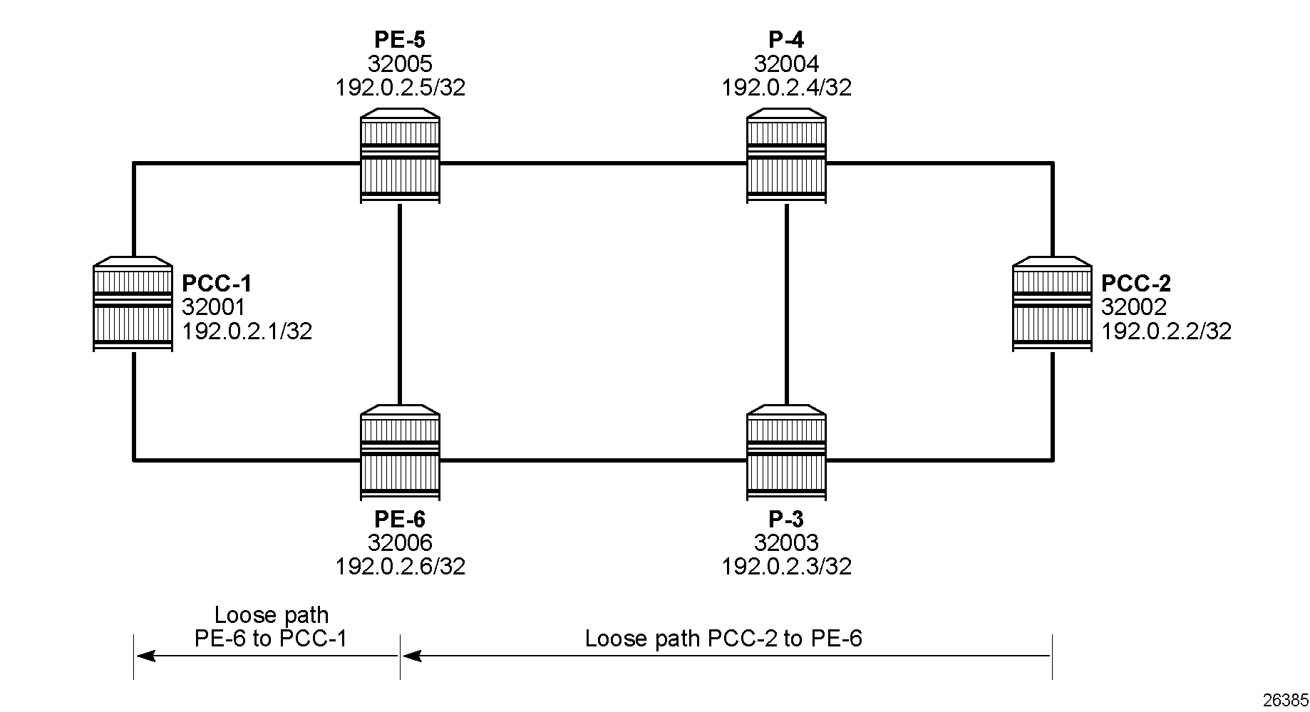
Explicit path with loose hops from PCC-2 to PCC-1 shows the concept of the loose path. The following configures the MPLS path containing a loose hop on PCC-2:
# on PCC-2:
    network-instance default {
        traffic-engineering-policies {
            explicit-paths {
                path PCC-controlled-loose-path {
                    hop 10 {
                        ip {
                            ip-address 192.0.2.6
                            hop-type loose
                        }
                    }
                }
            }
The following uncolored SR-MPLS TE policy references the explicit path with loose hops as the primary path:
# on PCC-2:
    network-instance default {
        traffic-engineering-policies {
            policy pol_loose-to-PCC-1 {
                policy-type sr-mpls-uncolored
                admin-state enable
                endpoint 192.0.2.1
                segment-list 1 {
                    admin-state enable
                    explicit-path PCC-controlled-loose-path
                    segment-list-type primary
                }
            }
The following shows the segments in segment list 1 of uncolored SR-MPLS TE policy "pol_loose-to-PCC-1":
--{ + running }--[  ]--
A:admin@PCC-2# info from state / network-instance default traffic-engineering-policies policy-database sr-uncolored policy * protocol-origin local segment-list 1 computed-segments segment * | as table | filter fields ip-address router-id is-loose sid-type sid-value/mpls-label

+---------------------+---------------------+------------------------+--------------+---------------+---------------------+---------------------+----------+----------------+----------------------+
|  Network-instance   | Policy policy-name  | Policy protocol-origin | Segment-list | Segment-index |     Ip-address      |      Router-id      | Is-loose |    Sid-type    | Sid-value mpls-label |
+=====================+=====================+========================+==============+===============+=====================+=====================+==========+================+======================+
| default             | pol_loose-to-PCC-1  | local                  |            1 |             1 | 192.0.2.6           | 192.0.2.6           | true     | node-sid       |                32006 |
| default             | pol_loose-to-PCC-1  | local                  |            1 |             2 | 192.0.2.1           | 192.0.2.1           | true     | node-sid       |                32001 |
+---------------------+---------------------+------------------------+--------------+---------------+---------------------+---------------------+----------+----------------+----------------------+
The first segment corresponds to the configured loose hop 192.0.2.6 and the second segment to the hop for the destination 192.0.2.1.
The head-end node PCC-2 translates the configured hop addresses into labels by examining the IS-IS TE database. The hop-to-label translation translates loose hops to node SIDs (N-SIDs).
The uncolored SR-MPLS TE policy is installed by the TTM into the tunnel table, alongside SR-ISIS advertised shortest path tunnels, for use by the TTM users, as follows:
--{ + running }--[  ]--
A:admin@PCC-2# show network-instance default tunnel-table ipv4

--------------------------------------------------------------------------------------------------------------------------------------------------------------------------------------------------------------------------------------
IPv4 tunnel table of network-instance "default"
--------------------------------------------------------------------------------------------------------------------------------------------------------------------------------------------------------------------------------------
+-------------------------------------------+----------------+----------+-----+----------+---------+--------------------------+--------------------------+--------------------------+------------------------------------------------+
|                IPv4 Prefix                |  Tunnel Type   |  Tunnel  | FIB |  Metric  | Prefere |       Last Update        |     Backup Nexthops      |     Next-hop (Type)      |                    Next-hop                    |
|                                           |                |    ID    |     |          |   nce   |                          |                          |                          |                                                |
+===========================================+================+==========+=====+==========+=========+==========================+==========================+==========================+================================================+
| 192.0.2.1/32                              | sr-isis        | 32001    | Y   | 210      | 11      | 2026-02-17T13:02:25.153Z |                          | 192.168.23.2 (mpls)      | ethernet-1/3.1                                 |
| 192.0.2.1/32                              | te-policy-sr-  | 1        | Y   | 210      | 8       | 2026-02-17T13:15:46.827Z |                          | 192.0.2.6/32 (sr-isis)   | ethernet-1/3.1                                 |
|                                           | mpls-uncolored |          |     |          |         |                          |                          |                          |                                                |
| 192.0.2.3/32                              | sr-isis        | 32003    | Y   | 100      | 11      | 2026-02-17T13:02:42.969Z |                          | 192.168.23.2 (mpls)      | ethernet-1/3.1                                 |
| 192.0.2.4/32                              | sr-isis        | 32004    | Y   | 100      | 11      | 2026-02-17T13:02:49.491Z |                          | 192.168.24.2 (mpls)      | ethernet-1/4.1                                 |
| 192.0.2.5/32                              | sr-isis        | 32005    | Y   | 110      | 11      | 2026-02-17T13:02:56.281Z |                          | 192.168.24.2 (mpls)      | ethernet-1/4.1                                 |
| 192.0.2.6/32                              | sr-isis        | 32006    | Y   | 110      | 11      | 2026-02-17T13:03:04.725Z |                          | 192.168.23.2 (mpls)      | ethernet-1/3.1                                 |
| 192.168.23.2/32                           | sr-isis        | 525000   | Y   | 0        | 11      | 2026-02-17T12:55:06.803Z |                          | 192.168.23.2 (mpls)      | ethernet-1/3.1                                 |
| 192.168.24.2/32                           | sr-isis        | 525001   | Y   | 0        | 11      | 2026-02-17T12:55:06.803Z |                          | 192.168.24.2 (mpls)      | ethernet-1/4.1                                 |
+-------------------------------------------+----------------+----------+-----+----------+---------+--------------------------+--------------------------+--------------------------+------------------------------------------------+
--------------------------------------------------------------------------------------------------------------------------------------------------------------------------------------------------------------------------------------
7 SR-ISIS tunnels, 7 active, 0 inactive
1 TE-POLICY-SR-MPLS-UNCOLORED tunnels, 1 active, 0 inactive
--------------------------------------------------------------------------------------------------------------------------------------------------------------------------------------------------------------------------------------
Layer 3 service provisioning – IP-VRF
Uncolored SR-MPLS TE policy tunnels are another MPLS tunnel type, and can be used for resolving BGP next hops for IPv4 routes within an IP-VRF.
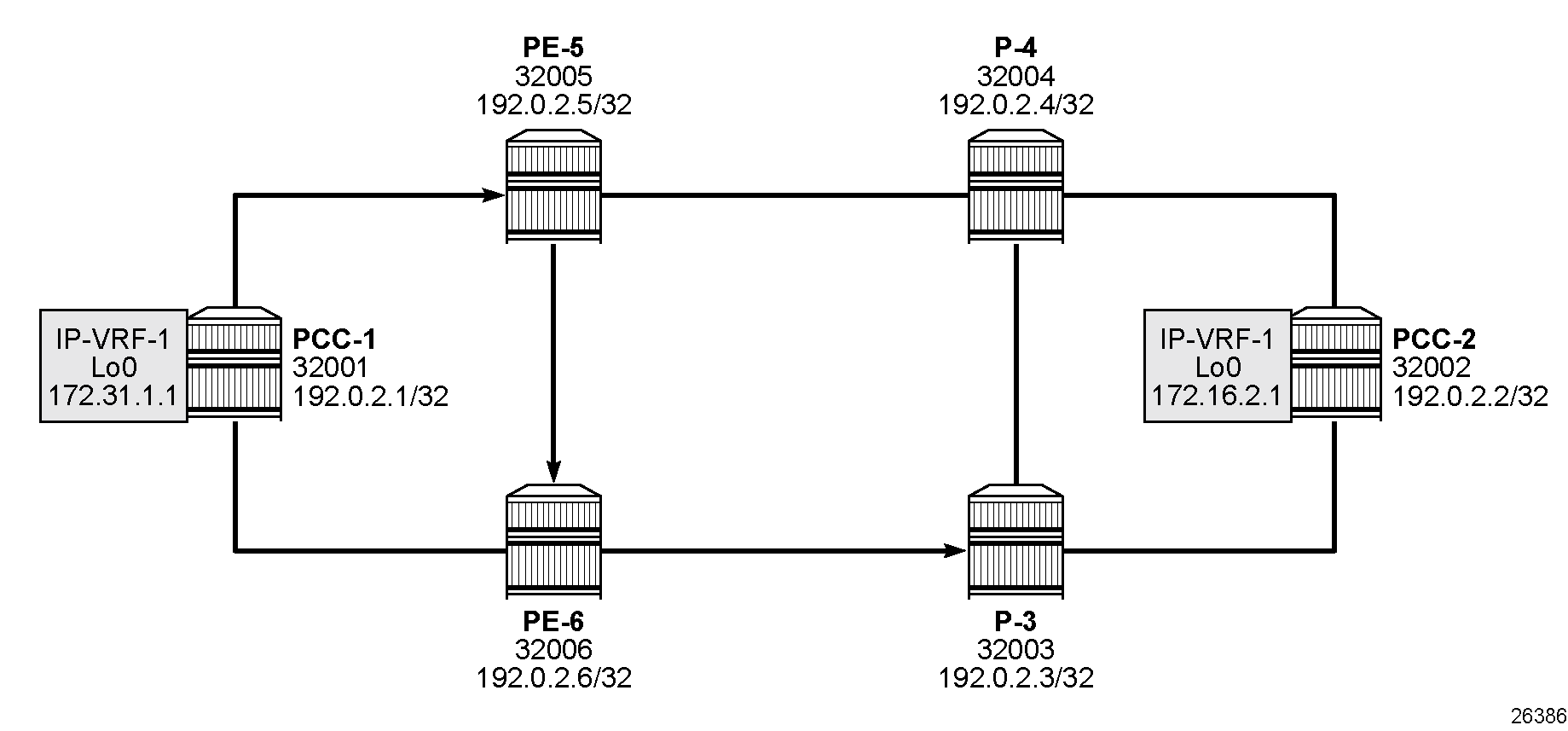
IP-VRF service schematic shows an IP-VRF service, configured on PCC-1 and PCC-2. The following configures the IP-VRF 1 on PCC-1. It includes a local interface using a /32 loopback address to be used to verify that routing is working correctly. The configuration on PCC-2 is similar.
# on PCC-1:
    network-instance "default" {
        protocols {
            bgp {
                admin-state enable
                autonomous-system 64496
                router-id 192.0.2.1            # on PCC-2: router-id 192.0.2.2
                afi-safi l3vpn-ipv4-unicast {
                    admin-state enable
                }
                group "IBGP" {
                    admin-state enable
                    peer-as 64496
                }
                neighbor 192.0.2.2 {            # on PCC-2: neighbor 192.0.2.1
                    admin-state enable
                    peer-group "IBGP"
                }
            }
        }
    }
    system {
        mpls {
            label-ranges {
                dynamic dynamic-services {      # label range for services
                    start-label 10000
                    end-label 19999
                }
            }
            services {
                network-instance {
                    dynamic-label-block dynamic-services
                }
            }
        }
    }
    interface lo0 {
        admin-state enable
        subinterface 0 {
            admin-state enable
            description "loopback interface in ip-vrf"
            ipv4 {
                admin-state enable
                address 172.31.1.1/32 {        # on PCC-2: 172.16.1.2/32
                    primary
                }
            }
        }
    }
    network-instance "ip-vrf-1" {
        type ip-vrf
        admin-state enable
        interface lo0.0 {
            interface-ref {
                interface lo0
                subinterface 0
            }
        }
        protocols {
            bgp-ipvpn {
                bgp-instance 1 {
                    admin-state enable
                    mpls {
                        next-hop-resolution {
                            allowed-tunnel-types [
                                te-policy-sr-mpls-uncolored
                            ]
                        }
                    }
                }
            }
            bgp-vpn {
                bgp-instance 1 {
                    route-distinguisher {
                        rd 192.0.2.1:1            # on PCC-2: rd 192.0.2.2:1
                    }
                    route-target {
                        export-rt target:64496:1
                        import-rt target:64496:1
                    }
                }
            }
The network-instance "ip-vrf-1" protocols bgp-ipvpn bgp-instance 1 mpls next-hop-resolution allowed-tunnel-types is set to te-policy-sr-mpls-uncolored, so that any BGP routes received have the next-hop resolved to an uncolored SR-MPLS TE policy LSP.
Examination of the IP-VRF route table on PCC-1 shows that the route prefix representing the IP address of the loopback address configured in IP-VRF 1 on PCC-2 is shown, and is resolved via the te-policy-sr-mpls-uncolored tunnel.
--{ + running }--[  ]--
A:admin@PCC-1# show network-instance "ip-vrf-1" route-table

-------------------------------------------------------------------------------------------------------------------------------------------------------------------------------------------------------------------------------------------------------------------------------------------
IPv4 unicast route table of network instance ip-vrf-1
-------------------------------------------------------------------------------------------------------------------------------------------------------------------------------------------------------------------------------------------------------------------------------------------
+---------------------------------------------+-------+------------+----------------------+----------+----------+---------+------------+---------------------------+---------------------------+---------------------------+---------------------------+
|                   Prefix                    |  ID   | Route Type |     Route Owner      |  Active  |  Origin  | Metric  |    Pref    |      Next-hop (Type)      |    Next-hop Interface     |  Backup Next-hop (Type)   | Backup Next-hop Interface |
|                                             |       |            |                      |          | Network  |         |            |                           |                           |                           |                           |
|                                             |       |            |                      |          | Instance |         |            |                           |                           |                           |                           |
+=============================================+=======+============+======================+==========+==========+=========+============+===========================+===========================+===========================+===========================+
| 172.16.1.2/32                               | 0     | bgp-ipvpn  | bgp_ipvpn_mgr        | True     | ip-vrf-1 | 220     | 170        | 192.0.2.2/32              |                           |                           |                           |
|                                             |       |            |                      |          |          |         |            | (indirect/te-policy-sr-   |                           |                           |                           |
|                                             |       |            |                      |          |          |         |            | mpls-uncolored)           |                           |                           |                           |
| 172.31.1.1/32                               | 5     | host       | net_inst_mgr         | True     | ip-vrf-1 | 0       | 0          | None                      | None                      |                           |                           |
+---------------------------------------------+-------+------------+----------------------+----------+----------+---------+------------+---------------------------+---------------------------+---------------------------+---------------------------+
-------------------------------------------------------------------------------------------------------------------------------------------------------------------------------------------------------------------------------------------------------------------------------------------
IPv4 routes total                    : 2
IPv4 prefixes with active routes     : 2
IPv4 prefixes with active ECMP routes: 0
-------------------------------------------------------------------------------------------------------------------------------------------------------------------------------------------------------------------------------------------------------------------------------------------
Connectivity is verified by sending a ping from the loopback interface within IP-VRF 1 on PCC-1 to the loopback address within IP-VRF 1 on PCC-2, as follows:
--{ + running }--[  ]--
A:admin@PCC-1# ping network-instance ip-vrf-1 172.16.1.2 -c 2

Using network instance ip-vrf-1
PING 172.16.1.2 (172.16.1.2) 56(84) bytes of data.
64 bytes from 172.16.1.2: icmp_seq=1 ttl=64 time=40.8 ms
64 bytes from 172.16.1.2: icmp_seq=2 ttl=64 time=49.3 ms

--- 172.16.1.2 ping statistics ---
2 packets transmitted, 2 received, 0% packet loss, time 1002ms
rtt min/avg/max/mdev = 40.837/45.051/49.265/4.214 ms
For completeness, a ping is sent in the opposite direction, between the PCC-2 IP-VRF 1 interface to PCC-1 IP-VRF 1, as follows:
--{ + running }--[  ]--
A:admin@PCC-2# ping network-instance ip-vrf-1 172.31.1.1 -c 2

Using network instance ip-vrf-1
PING 172.31.1.1 (172.31.1.1) 56(84) bytes of data.
64 bytes from 172.31.1.1: icmp_seq=1 ttl=64 time=48.8 ms
64 bytes from 172.31.1.1: icmp_seq=2 ttl=64 time=48.3 ms

--- 172.31.1.1 ping statistics ---
2 packets transmitted, 2 received, 0% packet loss, time 1001ms
rtt min/avg/max/mdev = 48.277/48.514/48.752/0.237 ms
Layer 2 service provisioning – VPWS
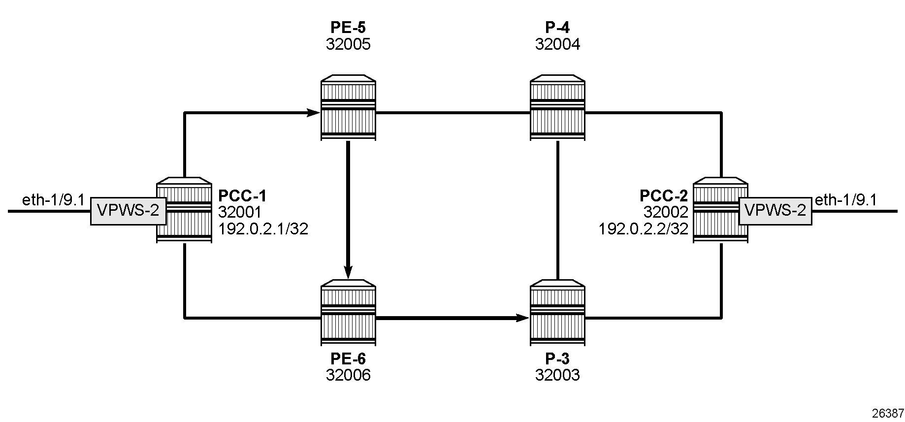
Uncolored SR-MPLS TE policy tunnels can also be bound as a transport tunnel within pseudowires. To illustrate this, consider the following example of a simple VPWS connected between PCC-1 and PCC-2, as shown in VPWS service schematic.
The pseudowires use T-LDP signaling, so an MPLS label range must be configured for LDP signaling, as follows:
# on all nodes:
    system {
        mpls {
            label-ranges {
                dynamic dynamic-ldp {
                    start-label 70000
                    end-label 79999
                }
                dynamic dynamic-services {      # same range as for IP-VRF
                    start-label 10000
                    end-label 19999
                }
            }
            services {
                network-instance {
                    dynamic-label-block dynamic-services
                }
            }
        }
    }
    network-instance default {
        protocols {
            ldp {
                admin-state enable
                dynamic-label-block dynamic-ldp
            }
The following shows the configuration of a PW on PCC-1 with far end on PCC-2 that can bind to an uncolored SR-MPLS TE policy. On PCC-2, a similar PW is configured.
# on PCC-1:
    tunnel {
        pseudowire-tunnel {
            tunnel pw-tunnel-PCC-1-PCC-2 {  # on PCC-2: tunnel pw-tunnel-PCC-2-PCC-1
                remote-system 192.0.2.2     # on PCC-2: remote-system 192.0.2.1
                allowed-tunnel-types [
                    te-policy-sr-mpls-uncolored
                ]
            }
        }
    }
The following VPWS is configured on PCC-1:
# on PCC-1:
    network-instance VPWS-2 {
        type vpws
        admin-state enable
        interface ethernet-1/9.1 {
            connection-point A
        }
        connection-point A {
        }
        connection-point B {
            pseudowire pw-PCC-1-PCC-2 {           # on PCC-2: pw-PCC-2-PCC-1
                admin-state enable
                pw-tunnel pw-tunnel-PCC-1-PCC-2   # on PCC-2: pw-tunnel-PCC-2-PCC-1
                signaling {
                    virtual-circuit-identifier 2  # must match on PCC-1 and PCC-2
                    tldp {
                    }
                }
            }
        }
Service verification
The following T-LDP session is established:
--{ + running }--[  ]--
A:admin@PCC-1# show network-instance default protocols ldp session

=============================================================================================================================
Net-Inst default LDP Sessions
-----------------------------------------------------------------------------------------------------------------------------
+---------------------------------------------------------------------------------------------------------------------------+
| Peer LDP ID                State           Adjacenc   Msg Sent   Msg Recv                   Last Oper State Change        |
|                                            y Type                                                                         |
+===========================================================================================================================+
| 192.0.2.2:0                operational     targeted   7          7                          2026-02-17T13:42:32.037Z      |
+---------------------------------------------------------------------------------------------------------------------------+
No. of sessions: 1
=============================================================================================================================
The following PW tunnel information is retrieved on PCC-1:
--{ + running }--[  ]--
A:admin@PCC-1# info from state / tunnel pseudowire-tunnel tunnel *

    tunnel pw-tunnel-PCC-1-PCC-2 {
        remote-system 192.0.2.2
        operational-tunnel-type te-policy-sr-mpls-uncolored
        operational-tunnel-id 1
        allowed-tunnel-types [
            te-policy-sr-mpls-uncolored
        ]
    }
On PCC-1, the following output shows that VPWS-2 is operationally up:
--{ + running }--[  ]--
A:admin@PCC-1# show network-instance VPWS-2 summary

+------------------------+------------+------------+------------+------------------------+------------------------------+
|          Name          |    Type    |   Admin    | Oper state |       Router id        |         Description          |
|                        |            |   state    |            |                        |                              |
+========================+============+============+============+========================+==============================+
| VPWS-2                 | vpws       | enable     | up         |                        |                              |
+------------------------+------------+------------+------------+------------------------+------------------------------+
The following output shows information about the connection points:
--{ + running }--[  ]--
A:admin@PCC-1# info from state with-context network-instance "VPWS-2" | grep "connection-point A {" --after-context 30


        connection-point A {
            oper-state up
            index 1
        }
        connection-point B {
            oper-state up
            index 2
            pseudowire pw-PCC-1-PCC-2 {
                admin-state enable
                oper-state up
                index 1
                destination-index 2283093814
                pw-tunnel pw-tunnel-PCC-1-PCC-2
                control-word false
                flow-label false
                flow-label-oper-state down
                signaling {
                    virtual-circuit-identifier 2
                    tldp {
                        virtual-circuit-type ethernet
                        ignore-mtu-mismatch false
                    }
                }
                local {
                    operational-ingress-vc-label 10001
                }
                remote {
                    operational-egress-vc-label 10001
                }
            }
        }
Similar output can be obtained for VPWS-2 on PCC-2.
Conclusion
Uncolored SR-MPLS TE policies extend the use of MPLS labels into traffic engineering applications. This chapter provides the configuration for router instantiated and controlled uncolored SR-MPLS TE policies along with some examples of the application in a IP-VRF and VPWS. The chapter also shows the associated commands and outputs that can be used for verifying and troubleshooting.